

CW Water-Cooled Laser Cleaner Maintenance: 9 Essential Steps
A practical maintenance guide for operators, maintenance technicians and buyers who need to protect cooling performance, optics, the delivery fiber, fume extraction and service records without applying unsafe generic settings.
 Maintenance is a system
When should a CW laser cleaner run, hold or stop?
Freeze the machine condition before changing anything. The decision below connects the observed condition to the correct response, the evidence needed and the boundary that prevents an unsafe restart.
No alarm, no moisture or damage, approved fluid is identified, and all displayed values match the documented normal baseline.
Inspect only the external items assigned to your role, record the result and release the machine through the site procedure.
Keep model and serial numbers, manual revisions, machine hours, coolant identity, ambient condition, alarms, photos and service history.
Stop for unknown fluid or moisture, repeated flow or temperature alarms, abnormal heat or odor, or a damaged interlock, fiber or window.
How does the water-cooling loop protect the laser?
A water-cooled cleaner is not only a laser plus a tank. The heat path includes coolant chemistry, flow, contact with cooled components, return temperature, refrigeration or heat exchange, and the chiller's air-side ability to reject heat.
The correct fluid leaves the reservoir at a controlled condition. Level, fluid identity, cleanliness and air in the loop all affect the starting point.
The source transfers waste heat to its approved cooling circuit. A finished machine may use separate high- and low-temperature circuits.
Some cleaning heads or optical assemblies have their own cooling needs. Never assume the source and head accept identical limits or fluid paths.
Flow carries picked-up heat back to the chiller. Kinks, trapped air, blocked filters, closed valves or leaks reduce that transport.
The condenser and fan transfer heat to room air. Dust, blocked clearance and hot-air recirculation can narrow cooling margin even when the water loop looks clean.
How should you respond to a CW cleaner maintenance symptom?
Describe what you see. The tool returns a safe planning route and the evidence to record. It does not calculate coolant, temperature, flow, pressure or service intervals.
Choose the closest observation and recent change. If more than one serious condition exists, use the most severe one.
No abnormal symptom is selected. Confirm the machine-specific coolant level, external hose condition, displayed baseline, chiller airflow, approved window check, fiber route and source capture before release.
What are the 9 CW water-cooled laser cleaner maintenance steps?
Each step separates what to inspect, why it matters, when to escalate and what evidence to keep. The sequence is intentionally model-specific: it tells you where to look without inventing settings.
Make the machine safe and perform a pre-start inspection
Read the released checklist before touching the machine. Inspect the work area, enclosure or controlled area, emergency functions, cables, connectors, hoses, visible fittings, warning labels and source-capture setup. Confirm that no one has defeated an interlock or left a temporary service condition in place. If maintenance exposes workers to unexpected energization, pressure, stored electrical energy or other hazardous energy, use the machine-specific isolation and the site lockout/tagout process—not only an emergency stop or software command.
Stop or escalateAny damaged safety device, liquid near electrical parts, burned odor, crushed delivery fiber, loose protected connector or unexplained service condition.
RecordDate, machine hours, operator, visible condition, original alarm code, isolation used and the person receiving the escalation.
Verify the approved coolant, quality, level and freeze protection
Identify the exact fluid named in the documentation for the delivered machine, laser source, head and chiller. Purified water, distilled water, deionized water and water-glycol mixtures are not interchangeable labels. Do not add automotive antifreeze, random alcohol, tap water or an internet recipe. Check the level only in the state and at the location defined by the manual. If the fluid identity, concentration, batch, age or prior top-up is unclear, place the machine on hold until the configuration is resolved in writing.
Stop or escalateUnknown or mixed coolant, discoloration, particles, biological growth, oil film, freeze history, repeated unexplained top-up or conflicting manuals.
RecordCoolant product, batch, date, quantity added, observed condition, ambient/storage history and authorization for any change.
Inspect the reservoir, hoses, fittings, pump area and loop
Follow the visible circuit from reservoir to supply, cooled components and return. Look for loose clamps, abrasion, swelling, flattening, kinks, sharp bends, wet joints, corrosion, trapped air indicators and signs that hoses rub against hot or moving parts. A falling level can have several causes, including leakage, evaporation in an open design or incomplete filling after service; the trend must be investigated rather than automatically diagnosed. Do not crack a fitting, run the pump dry or purge the loop with shop air unless the exact procedure permits it.
Stop or escalateUnknown moisture source, active drip, damaged hose, repeated bubbles, unstable pump sound, pressure loss or fluid close to optics/electrics.
RecordLeak location, level trend, photos, pump sound, hose condition, recent service and displayed values before shutdown.
Confirm temperature, flow, pressure, alarms and condensation protection
Compare displayed values with the normal baseline and the limits published for the exact system. A display is useful only when its units, sensors and normal operating range are known. Measure room temperature and relative humidity where the machine actually operates. Use the OEM dew-point table or control logic, keep cooled surfaces above dew point by the specified margin, and remain inside every source, head and chiller limit. Visible moisture is a stop condition; drying and restart must follow the approved procedure.
Stop or escalateRepeated low-flow/high-temperature alarm, oscillating reading, condensation, values outside the released range or a sensor that disagrees with physical evidence.
RecordOriginal alarm, supply/return displays, ambient temperature/RH, dew-point control mode, job load and when the deviation began.
Clean chiller air inlets, dust filters and the condenser
The water loop can be healthy while the chiller still overheats because room air cannot carry heat away. Check the required clearance, inlet screens, removable dust filters, fan condition and condenser face using only the access and cleaning method allowed by the chiller manual. Prevent hot discharge air from returning directly to the inlet. Dusty cleaning jobs, grinding nearby, high room temperature and blocked wall clearance may require more frequent external inspection than a clean laboratory installation.
Stop or escalateFan does not run, noise changes sharply, condenser is damaged, airflow remains weak after authorized cleaning, refrigerant work is indicated or temperature alarms return.
RecordFilter/condenser condition, cleaning date, ambient temperature, clearance, fan observation, replaced part and post-service thermal check.
Inspect the protective window and approved optical path
The protective window is a sacrificial barrier between process plume and costly downstream optics. Smoke, dust and spatter on it can absorb laser energy, create a hot spot, reduce delivered power and cause cracking. Use an external view, status monitor or approved cassette/window check defined by the head manufacturer; some sealed heads should not be opened daily. Handle optics only in the allowed service area with the exact window, coating, holder, wipes, solvent and sequence specified for that head. General optics advice is not permission to use a random shop solvent.
Stop or escalateCrack, chip, burn point, internal haze, damaged seal, contamination beneath the user-serviceable window or repeated rapid window failure.
RecordPart number, batch, orientation, photo, hours/jobs since installation, removed material, failure location and result of the controlled verification test.
Inspect the cleaning head, scanner, nozzle, delivery fiber and connectors
Check the outside of the head, scanner housing, nozzle or shroud, cooling connections and delivery path. Protect the cable from crushing, vehicle traffic, hot parts, torsion and bends below the specified radius. Do not lift the gun by the fiber or use it as a pull handle. A damaged jacket, sharp impact, abnormal head heat, scanner fault or suspect optical connection needs qualified inspection. Opening a sealed source/head or disconnecting a protected optical connector can expose contamination and embedded laser hazards.
Stop or escalateCrushed/kinked fiber, jacket damage, impact, loose protected interface, abnormal heating, scanner error, nozzle contact damage or suspected internal contamination.
RecordLocation and type of damage, photos, bend/route condition, fault code, recent handling event, head model and service owner.
Maintain fume extraction, filters, ducting and work-area cleanliness
Laser cleaning moves rust, paint, oxide, oil and other surface material into airborne particles and vapors. The hazard depends on the substrate, coating, contamination and process. Inspect the source-capture hood or nozzle, hoses, seals, airflow indicator, filter status, fire controls and waste-handling plan defined by the extractor manual and site hazard assessment. A filter loaded with paint, metal oxide or unknown residue may require controlled changeout and disposal. Do not compensate for weak capture by placing an uncontrolled fan that sends plume through the operator's breathing zone or into chiller air inlets.
Stop or escalatePlume escapes capture, alarm/indicator changes, filter is damaged, unusual odor/smoke appears, spark/fire risk is not controlled or removed coating is unknown.
RecordMaterial/coating, hood position, indicator value/status, filter stage/part, change date, waste classification and exposure-control action.
Complete scheduled coolant service, functional checks and records
Use the stricter of the OEM requirement and the site's condition-based plan. A clear-looking coolant does not justify extending a mandatory interval. During approved fluid service, control cleanliness, compatibility, filling, air removal and restart exactly as documented. After maintenance, verify the closed loop, alarms/interlocks, chiller response, head/fiber condition, extraction and a controlled reference cleaning test before production release. After transport, long storage, freezing, leakage, repair or a repeated alarm, add the special checks required by the manufacturer; a freeze event requires inspection for hidden pump, hose, heat-exchanger and cooled-component damage before restart.
Stop or escalateService cannot be completed within the published procedure, readings do not stabilize, a safety function fails, leakage returns or the reference result differs from baseline.
RecordWork order, exact fluid/parts, serials and batches, values before/after, fault history, person performing the work, verifier and open actions.
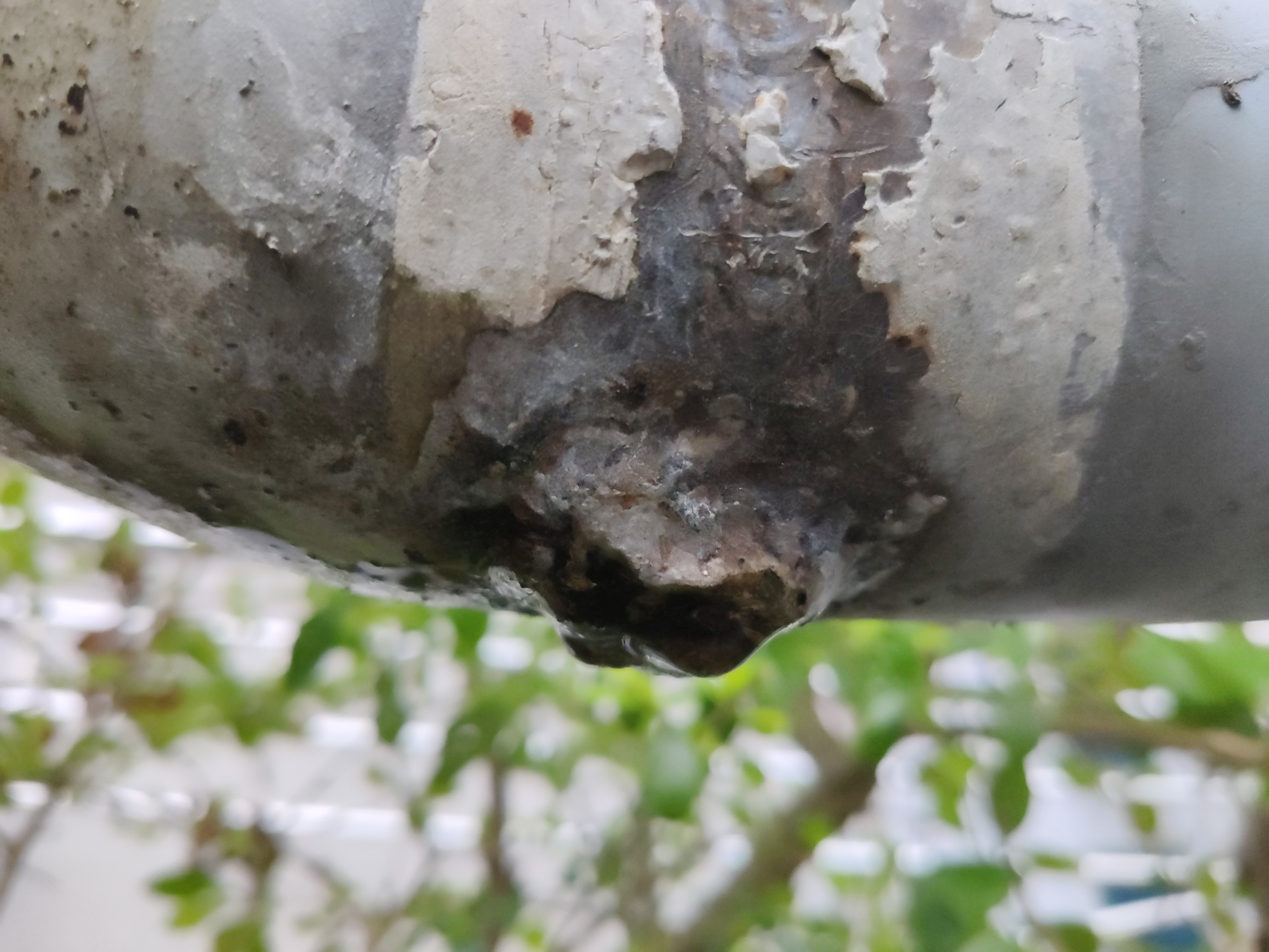
Is the wet hose leaking or collecting condensation?
A wet hose can be leaking, or it can be below the room's dew point and collecting moisture from the air. Both can place liquid near high-value optics and electrical systems. Surface appearance alone is not enough to release the machine.
Start with evidence. Identify where the water first appears, compare the reservoir level, inspect fittings without disturbing them, and record ambient temperature and relative humidity. A uniform film on several cool surfaces during humid weather suggests condensation, while a localized wet joint and falling level suggest leakage—but either finding still needs the approved correction and restart process.
How do you verify coolant and protective-window condition?
These tasks need different proof. A clear fluid can still be wrong for the system, and a lens-cleaning photograph does not define the correct method for a high-power cleaning head.


Coolant evidence to keep
Record more than “water looks clean.” Trace the delivered product and any top-up so a later alarm can be compared with the real service history.
- Exact product name, grade, batch and concentration where applicable
- Fill, top-up and replacement quantity and date
- Approved quality test, instrument and result
- Reservoir and line condition before and after service
- Ambient/storage/freeze history and any manual conflict
Optical evidence to keep
When a window fails early, preserve the part. Its location and contamination pattern can help connect the failure to plume capture, geometry, seals or deeper optical damage.
- Head and protective-window part numbers
- Window lot, installation date and orientation
- Before/after photos under consistent light
- Jobs, materials and coatings since installation
- Failure position, seal condition and verification result
Which tasks belong to the operator, technician or OEM?
Maintenance scope should be written into training, service documents and the machine handover. A competent operator is not automatically authorized to enter a refrigerant circuit, open a laser source or diagnose an energized cabinet.
Trained operator
- Perform the released external pre-start inspection.
- Read and record published display values and alarms.
- Check approved coolant level, visible moisture, fiber route and extraction status.
- Inspect the exterior or approved window cassette only as instructed.
- Stop, preserve evidence and escalate through the site procedure.
Qualified maintenance technician
- Apply site hazardous-energy and electrical procedures.
- Service allowed filters, condenser surfaces and cooling-loop items.
- Perform the specified fill, air-removal, fluid-change and restart process.
- Check permitted pumps, sensors, hoses, valves and safety functions.
- Trend alarms and verify the documented return-to-service test.
OEM-authorized service
- Open sealed laser sources or scanning heads.
- Disconnect protected optical interfaces or align internal optics.
- Service refrigerant, compressor or sealed heat-exchange circuits.
- Perform energized cabinet diagnosis where legally permitted.
- Modify safety systems, firmware limits or internal calibration.
How often should a water-cooled laser cleaner be maintained?
Use operating triggers rather than a made-up universal calendar. Frequency depends on the delivered configuration, beam-on hours, contamination load, ambient conditions, storage history and observed trend. The table is a planning template; the machine manuals and approved site plan set the actual tasks and intervals.
| Trigger | Typical planning focus | Evidence to review | Important boundary |
|---|---|---|---|
| Before each shift or job | External safety condition, visible moisture/leak, approved level/display check, fiber route, extraction and allowed protective-window check. | Open issues, prior shift alarms, machine hours, job material/coating and ambient condition. | Do not open a sealed head merely because the schedule says “inspect optics.” |
| During operation | Alarm state, thermal/flow trend, condensation, capture effectiveness, abnormal sound/odor/heat and cleaning consistency. | Time, job, settings identification, observed reading and physical symptom. | No alarm does not prove coolant, optics, extraction and early trends are healthy. |
| After a dirty job | Plume-exposed exterior, extraction loading, chiller intake area and approved window/cassette condition. | Removed coating, filter indicator, contamination photo and duration. | Shorten inspection only with a documented risk-based plan; solve the loading cause. |
| Periodic by hours/environment | Filters, condenser, coolant condition, hoses, connection condition, logs and spare stock. | Beam-on hours, dust/humidity trend, consumable life and repeat alarms. | Calendar time alone cannot represent different workshop loads. |
| At OEM interval or condition limit | Specified fluid service, filters, functional tests, calibration/verification and authorized internal service. | Manual revision, work order, parts/fluids, before/after values and release sign-off. | “It still looks clean” does not override a mandatory requirement. |
| After transport, storage, freeze, repair or alarm | Special inspection, hidden damage, loop integrity, dry-out, safety functions and controlled reference test. | Transport/storage temperature, shock event, repair details, original code and qualified inspection. | Do not restart after suspected freeze or moisture exposure until the approved inspection is complete. |
Review trends at a documented production cadence suitable for the site. If a filter, window or coolant condition reaches its limit early, shorten the inspection cycle and investigate the cause instead of treating frequent replacement as normal.
What do common chiller and cleaning symptoms mean?
Safe troubleshooting begins with the original code and physical evidence. It does not begin by increasing power, bypassing a switch or replacing several parts at once.
| Warning sign | Possible maintenance causes | Safe next step | Evidence worth keeping |
|---|---|---|---|
| High-temperature alarm | Dirty condenser, blocked airflow, hot-air recirculation, restricted water flow, heavy duty, sensor/refrigeration problem or unsuitable room condition. | Stop as required, record values and inspect only authorized external items. Escalate if the alarm persists. | Alarm code/time, ambient temperature, inlet/outlet condition, displayed values, filter/condenser photo and recent load. |
| Low-flow or water alarm | Low level, trapped air, leak, kinked hose, closed valve, blocked filter, pump issue or sensor fault. | Never bypass. Follow the shutdown and inspect the approved visible loop before qualified diagnosis. | Original code, level, recent fill/service, leak/air evidence, supply/return reading and pump sound. |
| Condensation | Cooled surface below dew point, humidity change, wrong control mode, unsuitable setpoint or missing/damaged insulation. | Stop laser operation, protect the area, identify moisture exposure and use OEM dry-out/restart guidance. | Ambient temperature/RH, wet locations, setpoint/control mode, photos and time since weather/HVAC change. |
| Cleaning slows or becomes uneven | Window contamination, plume/extraction change, scanner/head issue, focus/geometry change, material difference or source fault. | Do not compensate with more power before finding the cause. Compare the reference job and inspect approved items. | Before/after sample, material/coating, window photo, head status, program ID and alarm/log export. |
| Window burns repeatedly | Plume direction, poor capture, wrong window/holder, seal problem, process geometry, reflection or deeper optical contamination. | Preserve failed windows and place the system on hold for root-cause review. | Window part/batch, failure pattern, installation date, job orientation, material and hours to failure. |
| Weak source capture | Loaded filter, blocked/kinked hose, hood moved, fan fault, leakage or process/material outside the extractor basis. | Stop work that is not adequately controlled; use the extractor procedure and EHS/industrial-hygiene review. | Material/coating, capture position, indicator, filter history, duct condition and observed plume path. |
| Noise, odor or abnormal heat | Air in loop, pump/fan bearing, rubbing component, electrical issue, refrigerant fault or overheating connection. | Shut down through the approved process and use competent service. Do not continue to “see if it clears.” | Exact location, timing, sound/video, odor description, temperature indication, recent work and duty. |
| Damaged fiber or interlock | Impact, crushing, tight bend, torsion, traffic, hot material, unauthorized modification or connector disturbance. | Prevent emission, isolate as required and obtain authorized inspection before restart. | Photos, damage location, bend route, handling event, interlock state, head/source model and last good run. |
What should a CW laser cleaner maintenance log record?
A checklist proves that someone looked. A useful maintenance record connects machine identity, operating context, physical evidence, work performed and the final release decision.
Which spare parts require exact model matching?
“Looks the same” does not mean interchangeable. Wrong optics, seals, coolant or filters can create a new failure while appearing to solve an old one. Build the spare-parts list from the delivered bill of materials and manual—not from a generic machine wattage.
What maintenance information should the supplier provide before purchase?
Ask the supplier to define the installed configuration and the evidence needed to keep it reliable. A short answer such as “change pure water every few months” is not a complete maintenance plan.
What should you verify next?
These Oceanplayer Laser resources extend the maintenance decision into power selection, runtime planning, cleaning-head care, laser safety and fume extraction.
What else do operators ask about CW cleaner maintenance?
These are practical follow-up questions that affect daily release, top-up decisions, alarms and return to service.
Does a water-cooled laser cleaner need daily maintenance?
It normally needs a documented pre-start or pre-shift inspection, but not every service task is daily. Check the external safety condition, visible moisture, approved coolant level, displayed baseline, fiber route, chiller airflow and source capture at the interval assigned by the machine manual and site plan. Fluid replacement, internal service and calibration follow different model-specific or condition-based triggers.
Can I mix purified, distilled and deionized water when topping up the chiller?
Do not mix them because the names sound similar. Use the exact fluid and quality limit specified for the serial-numbered chiller, laser source and cleaning head. Record the product, batch and quantity added. If the existing fluid is unknown or the manuals conflict, hold the machine and obtain written direction before topping up.
Should I reset a low-flow alarm and continue cleaning?
No. Preserve the original alarm code and displayed values, then follow the approved shutdown and diagnostic process. Possible causes include low level, trapped air, leakage, a restricted hose, closed valve, loaded filter, pump problem or sensor fault. Inspect only the external items assigned to your role, and do not bypass or repeatedly reset the alarm.
Does clear-looking coolant mean it is still acceptable?
No. Clear appearance does not confirm the correct fluid identity, conductivity, concentration, contamination level or remaining service life. Compare the fluid with the exact OEM specification and approved test method. A visual check can reveal particles, discoloration or biological growth, but it cannot replace a required service interval or named quality test.
What should be checked after transport, long storage or possible freezing?
Use the manufacturer's special return-to-service procedure before restart. Record transport or storage temperature, duration, shock events and fluid condition; inspect the permitted cooling-loop, hose, connector, fiber and moisture points; then verify alarms, safety functions, chiller response and a controlled reference clean. Possible freezing or liquid exposure is a stop condition until qualified inspection is complete.

Our team creates practical guides on laser cleaning, welding, marking and industrial automation. We combine application experience with cited engineering sources to help manufacturers compare materials, evaluate processes and plan equipment trials with clearer requirements.
Which sources define the maintenance boundaries?
Manufacturer examples explain why the delivered model matters; they are not universal settings for every CW laser cleaner.
What should you send for a configuration review?
Send the machine, laser source, chiller and cleaning-head model and serial numbers, relevant manual revisions, job material, removed coating, shift profile, workshop temperature and humidity, alarm history, coolant record and clear photos. Oceanplayer Laser can help organize the maintenance questions, spare-parts list and handover evidence.