Volumetric contraction during solidification can reduce a casting’s dimensions by anywhere from 1.5% to over 7%, depending on the alloy — and uncontrolled metal casting shrinkage remains the single largest source of internal porosity defects across foundries worldwide. Shrinkage occurs because nearly all metals occupy less volume as a solid than as a liquid, creating voids if molten material can’t feed into contracting regions fast enough. This guide breaks down exactly why shrinkage happens at each stage of cooling, which alloys are most vulnerable, and the proven engineering methods — from riser design to solidification simulation — that keep your castings dimensionally accurate and structurally sound.
What Is Metal Casting Shrinkage and Why Does It Matter
Every metal occupies less space as a solid than it does as a liquid. That simple physical reality is the entire basis of metal casting shrinkage—the volumetric contraction that happens when molten alloy cools from its pouring temperature, passes through solidification, and continues cooling to ambient temperature. The total contraction can range from roughly 3.5% for gray iron to over 7% for steel and certain aluminum alloys, and ignoring even a fraction of a percent leads to parts that don’t fit, crack under load, or get scrapped outright.
Why should anyone in a foundry care beyond the obvious? Dimensional accuracy is the first concern. A casting destined for a CNC machining cell needs to arrive within a predictable size envelope; if shrinkage isn’t compensated in the pattern, the machinist runs out of stock to cut. But the deeper problem is internal. Uncontrolled shrinkage creates voids—pockets of empty space trapped inside the casting wall. These voids act as stress concentrators, slashing fatigue life and pressure-tightness. According to the American Foundry Society, shrinkage porosity remains one of the top three reasons castings fail quality inspection across the industry.
Then there’s cost. Every rejected casting burns energy, alloy, labor, and furnace time. Pattern rework alone can stall a production run for days. Understanding shrinkage behavior upfront—before metal hits sand—gives engineers the leverage to size risers correctly, adjust gating, and apply the right shrinkage allowance to the tooling. It turns a reactive scrap problem into a predictable design parameter.
The sections ahead break down exactly how contraction unfolds stage by stage, what drives it beyond normal limits, and the practical methods foundries use to keep it under control.

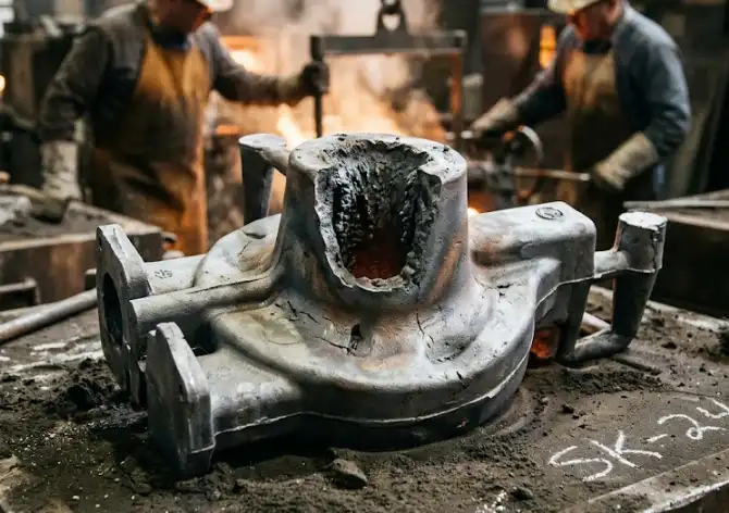
Diagram illustrating metal casting shrinkage as molten alloy contracts during solidification, revealing an internal shrinkage void
The Three Stages of Metal Shrinkage Explained
Metal casting shrinkage doesn’t happen all at once. It unfolds across three distinct phases, each governed by different thermal and physical mechanisms. Treating them as a single problem is a recipe for defective parts — the fix for one stage can actually worsen another.
Liquid Shrinkage
This first phase begins the moment molten metal is poured and starts cooling inside the mold cavity. The liquid contracts as its temperature drops toward the liquidus line. For gray iron, liquid shrinkage accounts for roughly 0.8–1.0% of volume; aluminum alloys can lose up to 1.5%. Because the metal is still fully fluid, this contraction is relatively easy to compensate — the riser simply feeds additional liquid into the cavity under gravity.
Solidification Shrinkage
Here’s where the real trouble starts. As the alloy transitions from liquid to solid between the liquidus and solidus temperatures, atoms lock into a crystalline lattice that occupies significantly less space. Steel shrinks about 3% by volume during this window. The partially solidified “mushy zone” — a spongy mix of dendrites and remaining liquid — makes feeding extremely difficult. Isolated liquid pockets that can’t receive fresh metal collapse inward, forming the internal voids foundries dread. According to the American Foundry Society, solidification shrinkage is the primary source of porosity-related casting rejections across the industry.
Solid-State (Patternmaker’s) Shrinkage
Once fully solid, the casting keeps contracting as it cools to room temperature. This phase is predictable and linear. Patternmakers compensate by oversizing the pattern — typically 1.0–2.5% depending on the alloy. Carbon steel needs about 2.0%, while gray iron requires only around 1.0% because graphite expansion during solidification partially offsets the thermal contraction. No riser or chill fixes this stage; it’s handled entirely at the pattern design level.
Understanding which stage dominates for a given alloy determines whether the solution lives in the gating system, the riser design, or the pattern shop.
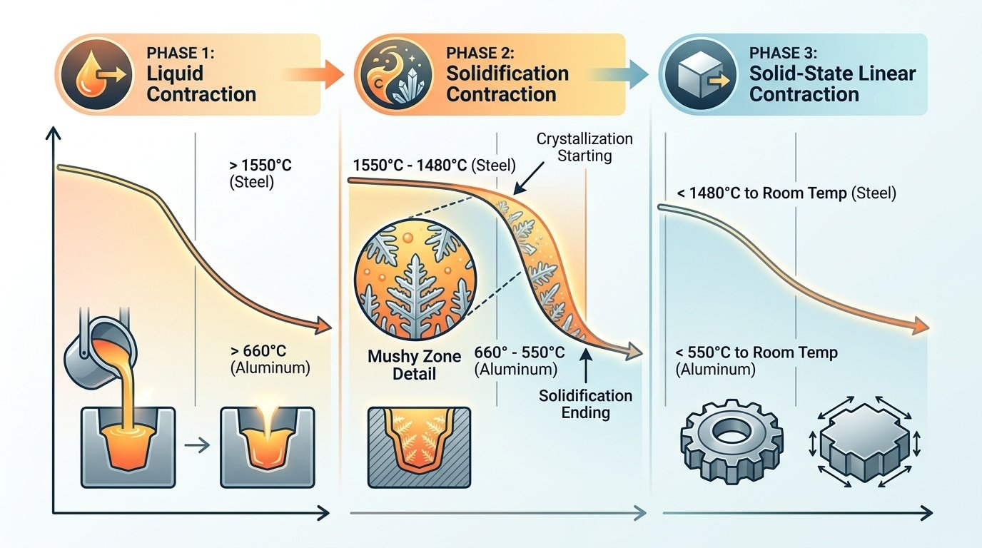
Three stages of metal casting shrinkage diagram showing liquid, solidification, and solid-state contraction phases with temperature ranges
Root Causes of Excessive Shrinkage in Castings
Some shrinkage is inevitable. Excessive shrinkage — the kind that scraps parts or causes field failures — almost always traces back to a handful of controllable variables working against each other.
Alloy Composition and Freezing Range
Alloys with a wide freezing range, like aluminum A356 (roughly 60°C between liquidus and solidus), solidify in a mushy, pasty manner that traps pockets of liquid deep inside the casting. Those isolated pools contract with no way to draw fresh metal in, and the result is dispersed microporosity. Narrow-freezing-range alloys such as pure aluminum or eutectic compositions tend to solidify with a clear front, making them far easier to feed. Tweaking silicon content in an Al-Si alloy by even 1–2% can shift the freezing behavior enough to dramatically change porosity levels.
Pouring Temperature and Mold Rigidity
Superheat matters more than many casters realize. Pouring 50°C above liquidus instead of 20°C means the liquid phase lasts longer, delaying skin formation and widening the thermal gradient across thick sections. That extra heat also softens sand molds, reducing their ability to resist metallostatic pressure. A rigid mold — green sand with high compaction or a chemite shell — resists expansion and helps maintain dimensional control. Weak molds flex, allowing the casting envelope to grow before solidification locks geometry in place.
Section Thickness and Feeding Path
Abrupt changes in wall thickness are the single biggest geometric contributor to metal casting shrinkage defects. A thick boss connected to a thin wall solidifies last at its center, but the thin wall freezes first and chokes off the feeding channel. According to the American Foundry Society, maintaining a taper ratio of at least 3:1 from riser to the last-to-freeze zone significantly reduces centerline porosity. Without that progressive taper, no amount of riser volume can compensate — the metal simply has no open path to reach the shrinking region.
These causes rarely act alone. High superheat combined with a wide-freezing-range alloy poured into a low-rigidity mold with abrupt section changes creates a compounding effect. Understanding how each variable interacts is the difference between predicting defects and chasing them after the pour.

Diagram illustrating how section thickness variations cause metal casting shrinkage by blocking the feeding path during solidification
Common Defects Caused by Poor Shrinkage Control
When metal casting shrinkage goes unmanaged, it leaves behind a predictable family of defects. Each one has a distinct signature — and confusing them with gas porosity or inclusions leads to misdiagnosis and wasted corrective effort.
Shrinkage Porosity
This is the most frequent offender. Irregular, dendritic voids form in the last regions to solidify, typically at thermal hot spots where no feed metal remains available. Under a microscope, shrinkage pores look jagged and interconnected — unlike gas porosity, which presents as smooth, spherical bubbles. If you section a suspect casting and see rough, sponge-like cavities clustered near thick-to-thin transitions, that’s shrinkage.
Hot Tears and Centerline Shrinkage
Hot tears appear as ragged cracks along grain boundaries while the alloy is still semi-solid. They happen when the casting’s geometry restrains normal thermal contraction. Centerline shrinkage is different: a narrow void running along the geometric center of a section, caused by solidification fronts meeting without adequate liquid feed. Both defects are structural. Parts with either flaw rarely survive pressure testing.
Pipe Formation and Surface Sinks
Pipe shrinkage creates a funnel-shaped cavity that extends downward from the top surface of a riser or thick section — visible to the naked eye. Surface sinks are subtler: shallow depressions on exterior walls where subsurface voids pull the solidifying skin inward. A sink that measures just 0.5 mm deep can indicate a much larger internal void beneath it.
Telling Shrinkage Apart from Gas Defects
The key diagnostic difference is geometry. Gas pores are round and distributed randomly. Shrinkage voids are angular, clustered at hot spots, and often follow interdendritic paths. X-ray inspection makes the distinction clear — shrinkage appears as irregular dark patches with rough edges, while gas shows up as distinct round spots. The ASTM E2868 standard provides reference radiographs that help classify these indications consistently across inspection teams.
Shrinkage Allowance Values for Common Casting Alloys
Pattern makers add extra dimensions to compensate for the contraction a casting undergoes as it cools to room temperature. Getting those numbers wrong — even by a fraction of a percent — can push critical features out of tolerance. The table below summarizes widely referenced linear shrinkage allowances for common alloys.
| Alloy | Linear Shrinkage (%) | Volumetric Shrinkage (%) |
|---|---|---|
| Gray Iron (Class 30–40) | 0.8 – 1.0 | 2.5 – 3.5 |
| Ductile Iron | 0.8 – 1.0 | 3.5 – 5.5 |
| Carbon Steel (WCB) | 1.5 – 2.0 | 5.0 – 7.0 |
| Stainless Steel (CF8/CF8M) | 2.0 – 2.6 | 5.5 – 7.5 |
| Aluminum Alloys (A356, 319) | 1.2 – 1.5 | 3.5 – 6.0 |
| Copper Alloys (C83600, C95400) | 1.5 – 2.1 | 4.0 – 6.5 |
| Zinc (Zamak 3/5) | 1.0 – 1.3 | 3.0 – 4.5 |
Gray iron stands out because graphite expansion during solidification partially offsets contraction, keeping its metal casting shrinkage rate lower than steel. Ductile iron shows similar linear numbers, yet its volumetric shrinkage is notably higher — a detail that catches many engineers off guard when sizing risers.
Published values are starting points, not gospel. A long, thin bar contracts more freely than a heavily cored housing constrained by rigid sand cores. Thick-to-thin transitions, internal bosses, and mold rigidity all shift actual shrinkage away from textbook figures. The American Foundry Society recommends validating allowances with first-article measurements and adjusting patterns accordingly. In practice, experienced pattern shops often maintain alloy-specific correction factors tuned to their own mold systems and pouring temperatures.
To calculate a pattern dimension, multiply the finished casting dimension by (1 + shrinkage rate). For a 500 mm carbon steel feature at 1.8% allowance, the pattern dimension becomes 509 mm. Simple math — but choosing the right percentage demands judgment shaped by part geometry and constraint conditions.
Using Risers and Chills to Control Directional Solidification
Risers and chills work as a team. One adds heat; the other removes it. Together, they steer the solidification front so that the last pocket of liquid metal freezes inside a sacrificial reservoir — the riser — rather than inside the casting wall where it would leave a void.
How Risers Compensate for Volumetric Contraction
A riser is essentially a molten-metal battery. It stays liquid longer than the section it feeds, supplying extra volume as the casting contracts during the liquid-to-solid transition. Sizing matters enormously: an undersized riser solidifies too early and starves the casting. The classic Caine’s method and modulus method both relate riser volume to the casting section’s modulus (volume ÷ cooling surface area). A riser’s modulus must exceed the casting section’s modulus by at least 20% to guarantee it freezes last. Placement follows a simple rule: position the riser at the thickest, last-to-solidify region, and ensure an unobstructed feed path between riser and casting.
Chills: Forcing the Freeze Direction
Chills are metal inserts — typically iron or copper blocks — placed against the mold wall to accelerate local cooling. They flip a section from “last to freeze” to “first to freeze,” pushing the solidification front progressively toward the riser. External chills sit on the mold surface. Internal chills are placed inside the mold cavity and actually melt into the casting, so alloy compatibility is critical.
The goal is directional solidification: a smooth, unbroken freeze front moving from thin extremities toward the riser. Without chills, isolated hot spots can form between the riser and far sections, creating pockets that shrink independently — the classic source of metal casting shrinkage porosity. A well-placed chill eliminates that hot spot by pulling heat out faster than the surrounding sand can.
Progressive vs. Directional Solidification
Progressive solidification means the entire casting freezes inward at roughly the same rate. Directional solidification means one end freezes first and the front sweeps toward the riser. Most sound castings need directional behavior. Chills create it; risers reward it. Skip either tool, and you’re gambling on geometry alone.
Gating System Design Best Practices for Minimizing Shrinkage
The gating system does more than deliver molten metal into a mold cavity. It dictates fill sequence, thermal gradients, and whether liquid feed paths stay open long enough to compensate for volumetric contraction. A poorly designed gate can undermine even the best riser placement, turning an otherwise sound casting into scrap.
Bottom gating fills the cavity smoothly, reducing turbulence and oxide entrainment. The trade-off? Metal enters at the lowest point and heats the mold floor first, which can flatten the thermal gradient and starve upper sections of directional feed. Top gating reverses this — it establishes a strong top-to-bottom gradient that favors progressive solidification toward the riser, but risks splash erosion and gas pickup during fill. Many foundries split the difference with horn gates or side-entry designs that balance fill quality against thermal profile.
Runner-to-gate area ratios matter more than most engineers realize. A pressurized system (ratio around 1:0.75:0.5 for sprue:runner:gate) accelerates metal through the ingate, keeping flow temperature high and reducing premature freezing in thin sections. An unpressurized system (1:2:2 or wider) slows velocity and suits alloys prone to dross, like aluminum A356. Choosing the wrong ratio for your alloy can choke feed channels right when metal casting shrinkage demands the most liquid supply.
Simulation software — tools like MAGMASOFT or ProCAST — lets engineers visualize fill patterns and solidification fronts before cutting a single core box. Running 15–20 virtual iterations to optimize gate location, size, and angle is now standard practice at high-volume shops, and it routinely cuts first-article rejection rates by 30–50%.
Advanced Prevention Techniques and Simulation Tools
Risers and chills handle the physics. Simulation software lets you see the physics before you pour a single heat. Tools like MAGMASOFT, ProCAST, and SOLIDCast model filling patterns, thermal gradients, and solidification fronts in three dimensions — predicting exactly where metal casting shrinkage porosity will form. A foundry running these simulations can iterate through 20 or 30 riser configurations in a single afternoon, a process that used to consume weeks of trial castings and destructive testing.
Behind much of this software sits Chvorinov’s rule. It relates solidification time to the volume-to-surface-area ratio (the casting modulus). The practical takeaway: a riser must have a higher modulus than the section it feeds, or it freezes first and becomes useless. Modulus-based feeding calculations give engineers a quick analytical check even before they open a simulation package.
Sleeves and Alloy Modification
Exothermic and insulating riser sleeves extend the liquid life of feed metal by 40–60% compared to a bare sand riser. That means smaller risers, better yield, and lower melting costs. Leading foundries pair sleeves with alloy modification — adding strontium to Al-Si alloys or rare-earth elements to ductile iron — to shift solidification morphology and distribute residual shrinkage into harmless micro-porosity rather than concentrated macro-voids.
The real competitive edge comes from integrating all of these tools into a single workflow. Process engineers run a simulation, validate modulus calculations against the software output, specify sleeve types in the tooling package, and lock in alloy chemistry targets — all before pattern production begins. That front-loaded approach catches problems when fixes cost nothing more than a revised CAD file.
Frequently Asked Questions About Metal Casting Shrinkage
Which metals shrink the most during casting?
Aluminum alloys top the list, with volumetric shrinkage reaching 6.5–8.5% in some grades. Steel follows closely at roughly 5–7%. Gray cast iron is the outlier — its graphite expansion during solidification partially offsets contraction, bringing net shrinkage down to around 1.5–2.5%. Copper-based alloys fall somewhere in between, typically 4–6% depending on tin or zinc content.
Can shrinkage be completely eliminated?
No. Every alloy contracts as it transitions from liquid to solid; that’s thermodynamics, not a process flaw. The real goal is to relocate shrinkage into sacrificial areas — risers, feeders, overflow pads — where it gets machined away. A well-designed casting doesn’t eliminate metal casting shrinkage. It hides it where nobody will ever notice.
How does shrinkage differ from contraction?
“Shrinkage” usually refers to the volume reduction during solidification itself, while “contraction” describes the continued dimensional decrease as the solid casting cools to room temperature. Pattern makers account for both, but they address them separately: shrinkage gets managed through risering and feeding, contraction gets handled through shrinkage allowances built into the pattern dimensions.
What’s the difference between shrinkage porosity and gas porosity?
Cut a defect open. Shrinkage porosity looks dendritic and jagged — like tiny interconnected tunnels following the last metal to freeze. Gas porosity appears as smooth, round bubbles. Under X-ray, the distinction is even clearer. The ASTM E155 reference radiographs provide side-by-side comparisons that make identification straightforward.
How do you inspect castings for hidden shrinkage?
Industrial X-ray (radiographic testing) remains the gold standard for internal voids. Ultrasonic testing works well for thick-walled sections. For surface-connected microporosity, dye penetrant testing catches what the naked eye misses. Critical aerospace and pressure-vessel castings often require all three methods in combination.
Key Takeaways for Controlling Shrinkage in Your Castings
Every casting shrinks. The goal was never to eliminate contraction — it was to predict it, account for it, and direct it where it can’t do harm. Here’s what matters most.
- Master the three stages. Liquid shrinkage, solidification shrinkage, and solid-state contraction each demand a different response. Liquid shrinkage needs adequate volume in the feeding system. Solidification shrinkage needs directional control through risers and chills. Solid-state contraction needs correct pattern allowances — typically 1% to 2.5% depending on the alloy.
- Get allowance values right at the pattern stage. A 0.3% error on a 600 mm dimension means nearly 2 mm of deviation. Check alloy-specific data from sources like the American Foundry Society rather than relying on generic tables.
- Design feeding systems with purpose. Risers should solidify after the casting section they feed. Chills should accelerate freezing at heavy sections to push the last-to-freeze zone toward the riser. Gating layout controls fill pattern, thermal gradients, and ultimately where porosity ends up.
- Simulate before you pour. Tools like MAGMASOFT and ProCAST can flag shrinkage porosity locations, predict hot spots, and let you iterate on riser placement digitally — saving weeks of trial-and-error on the shop floor.
Controlling metal casting shrinkage comes down to a disciplined chain: accurate material data feeds correct pattern dimensions, which pair with a well-designed feeding system, validated by simulation. Break any link and scrap rates climb.
If your current rejection rate from shrinkage-related defects exceeds 3% to 5%, revisit your riser sizing and solidification sequence first — those two areas account for the majority of correctable problems. For complex geometries or alloys you haven’t poured before, bring in a foundry engineering specialist early in the design phase. The cost of expert input is a fraction of the cost of reworking tooling after first article inspection failures.
See also
Weld Cleaning Machine for Carbon Steel – How to Choose the Right One
How to Tell Aluminum from Stainless Steel: Shop Guide
6 Best Most Common Aluminum Alloys for Fabrication (Weldability & Uses)
Welding Cast Iron: Safe Methods & Pro Tips
How to Heliarc Weld Carbon Steel: Step-by-Step Troubleshooting


