

Fiber Laser Cleaner Wavelength and Power: What 1064 nm and Watts Really Mean
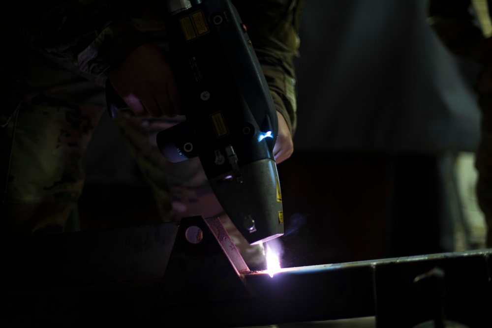
Most industrial fiber laser cleaners work near 1064 nm. That tells you the color of the invisible laser light—not whether the machine will clean your part well. Real performance depends on how power is packaged into pulses or continuous output, focused onto the surface, and moved across the job.
Confirm the exact source. The near-infrared beam is invisible and material absorption varies.
Average power alone does not define pulse energy, peak power, spot dose or substrate risk.
Build a window that removes the contaminant while staying below the allowed base-surface change.
Require your real alloy, coating, geometry, finish requirement and inspection method.
Which laser-cleaner specification should you verify first?
Start with the missing fact that can change the equipment choice. Do not move to price comparison while the source identity, valid operating map, acceptance method or safety boundary is still undefined.
| Quotation or job condition | Verify first | Evidence to request | Stop the comparison when |
|---|---|---|---|
| The quotation says only “1064 nm fiber laser” | Exact source identity and output mode | Manufacturer, model code, datasheet revision, central wavelength and pulsed or CW architecture | The supplier cannot identify the installed source or changes it without written approval |
| The quotation says “200 W” or “300 W pulsed” | How average power is divided into pulses | Valid pulse-energy, frequency and pulse-width combinations plus beam quality and cleaning-head data | The quotation combines independent maximum values that cannot operate together |
| The goal is faster large-area cleaning | Accepted production rate, not scan speed | Timed trial on representative parts, pass count, usable width, temperature and inspection result | Speed is shown only on an easy coupon or without the same acceptance endpoint |
| The substrate is thin, textured, valuable or dimension-sensitive | Damage limit and inspection method | Before-and-after roughness, profile, microscopy, dimensional or downstream performance evidence | “No damage” is supported only by a distant photograph or visual opinion |
| The machine will be handheld or used with an open beam | Accessible-beam and plume controls | Site risk assessment, enclosure or controlled-area plan, interlocks, extraction and wavelength-rated protection | The safety design depends on eyewear alone or ignores reflections and airborne contamination |
Swipe the table sideways to see all four decision columns.
1064 nm identifies the source—not the finished process
Many industrial cleaning systems use ytterbium fiber sources with a central wavelength near 1064 nanometers. That wavelength is in the near-infrared region. It is outside normal human vision, so a bright-looking work area does not tell you where the hazardous beam or reflection is.
The wavelength influences how the beam interacts with the coating and the base material. Dark rust, oxide, paint and carbon deposits may initially absorb the beam differently from bright metal exposed underneath. As the surface becomes cleaner, the optical coupling can change. A setting that removes the first layer quickly can become too weak, too reflective or too aggressive later in the pass.
A 1064 nm label does not prove that a cleaner is suitable. Ask what the contaminant absorbs, what the substrate reflects, and how the process stops before unacceptable surface change.
Why “How many watts?” is the wrong first question
Average power tells you how much laser energy leaves the source each second. It does not tell you how that energy reaches the surface. Five linked decisions turn a nameplate wattage into a cleaning result.
Wavelength, average power, output mode, beam quality and stability set the available starting envelope.
Pulse energy, duration and repetition rate determine how energy is divided over time.
Lens, focus, working distance and spot size determine how the beam is distributed in space.
Speed, hatch spacing, overlap, field size, pattern and passes determine repeated exposure.
Contaminant, thickness, alloy, finish, geometry and temperature decide what the energy actually does.
Four relationships that make a datasheet useful
These equations are planning relationships. They help you compare source architectures and catch incomplete quotations. They do not create a safe production recipe by themselves.
Pavg = Ep × f
Average power equals pulse energy multiplied by pulse frequency. If power stays fixed, increasing frequency usually reduces the energy available per pulse.
Ppeak ≈ Ep ÷ τ
A shorter pulse can create higher simplified peak power from the same pulse energy. Real pulse shape may not be perfectly rectangular.
F = Ep ÷ A
Fluence is pulse energy divided by illuminated area. Focus and beam profile therefore matter as much as the source value.
H ≈ P ÷ (v × h)
This nominal area-energy relationship uses scan speed and hatch spacing. It does not account for absorption, pulse overlap, edges or acceleration.
Pulsed and CW cleaners deliver heat differently
Neither mode is automatically “better.” The correct choice depends on the removal rate, surface condition, heat sensitivity and quality acceptance you must achieve.
Energy arrives in short events
Pulse energy, pulse duration and frequency can create high instantaneous intensity while limiting the time available for heat to spread. This gives the engineer more ways to separate contaminant removal from substrate damage.
- Useful when surface preservation, texture or heat control is important.
- Common in mold cleaning, precision parts, selective coating removal and pre-bond preparation.
- Requires a valid combination of frequency, pulse width and power—not independent maximum values copied from a datasheet.
Energy arrives continuously
A continuous-wave beam behaves more like a moving heat source. High average power can support rapid removal across large, robust metal surfaces, but travel speed, line overlap and dwell at reversals become critical.
- Useful when throughput on heavy rust, thick coating or large fabricated structures dominates.
- Often selected for shipyard, steel structure and large-area maintenance work.
- Requires careful control of heat accumulation, corners, thin sections and reflective exposure.
See how the parameters are connected
Change one value at a time. The tool shows simplified mathematical relationships so you can read a supplier datasheet more intelligently. It does not recommend a cleaning recipe or define a safe threshold.
Use these numbers to compare relationships. A real process must be validated on the actual contaminant and substrate, with an inspection method that detects unacceptable surface change.
Two 300 W lasers can behave very differently
Same wattage, different pulse architecture
JPT's published CL2 family illustrates why a buyer must ask for the exact source model. Its 300 W models share a listed central wavelength of 1064 nm, but the published maximum pulse energy and beam quality vary by model.
A narrow, lower-M² beam and a larger, higher-M² mode do not distribute energy in the same way after the scan optics. The system integrator must pair the source, cleaning head, lens, field size and process window.
| Published JPT model | Average power | Max pulse energy | Beam quality M² | Central wavelength |
|---|---|---|---|---|
| YDFLP-CL2-300-1-A | 300 W | 2 mJ | 1.5 | 1064 nm |
| YDFLP-CL2-300-5-A | 300 W | 5 mJ | 5 | 1064 nm |
| YDFLP-CL2-300-10-A | 300 W | 15 mJ | 12 | 1064 nm |
Source: JPT CL2 200–300 W official specifications, accessed September 2, 2026. Values apply to the listed models, not to all 300 W cleaners.
The cleaning head decides where the watts go
The source creates the beam. The scan head and optics turn it into a path on the part. A process can fail even when the source values are correct if focus, speed, hatch or edge behavior changes.
Wider hatch spacing
More area may be covered per unit time, but insufficient overlap can leave stripes or islands of contamination. The true cleaning width may differ from the programmed pattern width.
Tighter hatch spacing
More overlap can improve coverage, but it also repeats exposure and can increase heat accumulation. Corners and scan reversals may receive extra dwell.
Settings that must travel together
- Focus and working distance: change spot size and intensity.
- Scan speed: changes how long energy interacts with each path segment.
- Hatch spacing: changes cross-line overlap and nominal area dose.
- Pattern and field size: affect edge behavior, acceleration and uniformity.
- Pass count: may separate controlled layer removal from one aggressive pass.
Match the power architecture to the cleaning requirement
The table is a starting direction for trials, not a universal prescription. Surface acceptance and real samples determine the final route.
| Job condition | What usually controls the decision | Starting direction to compare | Evidence to require |
|---|---|---|---|
| Precision mold or textured surface | Protecting profile, dimensions and finish while removing residue | Pulsed source with controllable pulse parameters and repeatable focus | Microscopy, roughness or profile comparison before and after |
| Light rust on fabricated parts | Consistent removal rate without overheating thin edges | Pulsed or lower-power CW comparison, based on thickness and throughput | Residual contamination check plus base-surface inspection |
| Heavy rust or thick coating on robust steel | Area rate, multiple passes, fume load and heat accumulation | Higher-power CW and pulsed options compared on cost per accepted area | Timed area trial, temperature observation and extraction loading |
| Pre-weld or pre-bond preparation | Cleanliness, oxide state, repeatability and downstream joint performance | Controlled pulsed processing with a defined acceptance method | Joint tests, surface chemistry or qualified process evidence |
| Selective paint removal | Stopping at a primer or substrate without visible or hidden damage | Pulsed source with multiple controlled passes and stable positioning | Layer-removal proof across thickness and color variation |
| Automated production cell | Duty cycle, robot path, focus tolerance, extraction and process monitoring | Source and head selected as an integrated system, not separate wattage items | Cycle study, repeatability run and change-control plan |

A laboratory recipe is not yet a production process
In production, lens contamination, standoff drift, field-position effects, part tolerance, operator technique and extraction loading can move the actual dose away from the trial condition.
An automated cell may improve repeatability, but only if the process includes part location, focus control, fixture access, scan-path version control, maintenance checks and a clear response when the result drifts.
Build a cleaning window in seven steps
A useful process window connects laser settings to a pass/fail result. It also defines when the trial is no longer representative and must be repeated.
State what “clean” means, how much substrate change is allowed and how both will be measured.
Match alloy, coating, thickness, age, geometry, finish and contamination range—not only a flat coupon.
Record exact source model, head, lens, field size, working distance, extraction and part presentation.
Change planned factors methodically. Do not raise power while also changing focus, speed, hatch and passes.
Confirm contaminant removal and check for roughness, color, melting, pitting, distortion or downstream performance loss.
Choose a stable middle condition and define allowed ranges for critical settings, focus, cleanliness and consumable condition.
Verify across lots, operators, field positions, duty cycle and maintenance intervals before production release.
Read the symptom before changing the watts
| Observed result | Likely process questions | Controlled checks |
|---|---|---|
| Residual stripes or islands | Is the true cleaned width smaller than the programmed path? Is hatch spacing too wide or focus drifting? | Measure track width, confirm working distance, inspect scanner calibration and review overlap. |
| Dull, rough, colored or pitted base metal | Has local fluence or repeated dose crossed the acceptable surface-change limit? | Reduce exposure systematically, inspect edges/reversals and compare multiple-pass versus single-pass strategies. |
| Charring or redeposition | Is the coating decomposing faster than fumes and particles are captured? | Review extraction position and airflow, scan direction, pass depth and surface temperature. |
| Fast center, weak field edges | Does spot size, focus or scanner behavior change across the field? | Map results by field position, reduce field size if needed and confirm lens/head alignment. |
| Results drift during the shift | Are optics, extraction filters, temperature, source output or standoff changing? | Add start-up coupons, lens checks, filter differential-pressure checks and scheduled verification. |
More aggressive settings also change the hazard
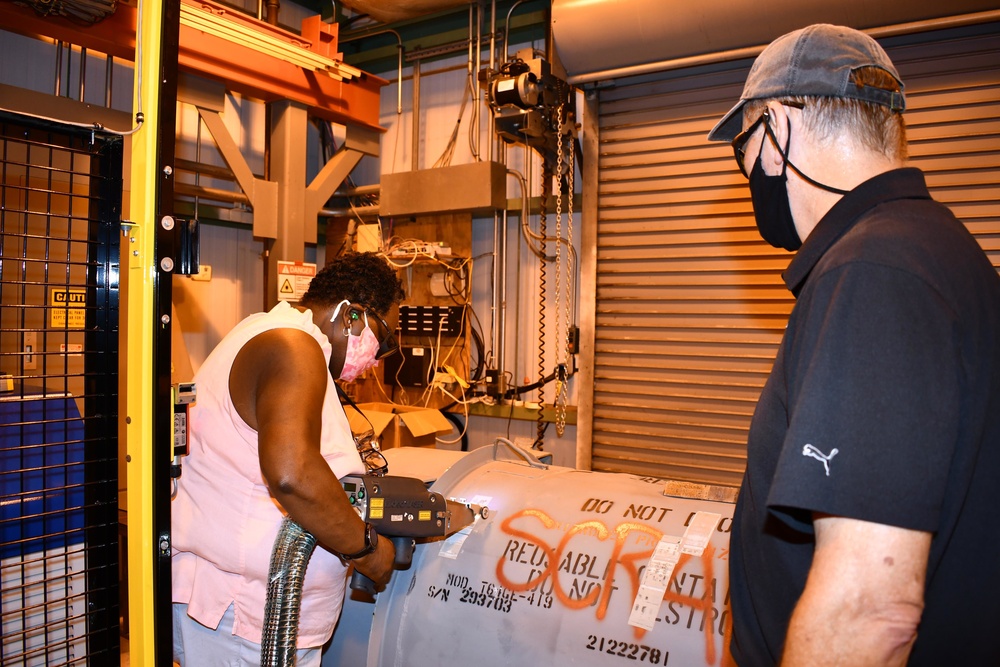
A near-infrared fiber laser beam is invisible, and specular reflections from metal can redirect hazardous energy. The cleaning plume may contain particles, oxides and decomposition products from paint, oil or coatings. The hazard therefore depends on the beam, material and process—not only the machine label.
Use an engineered enclosure where practical. A qualified laser safety professional should define controlled access, interlocks, beam stops, windows, warning systems, training and wavelength-rated protection. Local source capture should be designed for the actual plume and verified during trials.
- the material or coating changes;
- the lens, field or working distance changes;
- open-beam work or a new fixture is introduced;
- power, pulse mode or robot path moves outside the qualified window;
- extraction or filtration changes.
Reference guidance: NIST Laser Safety Program and OSHA laser hazard assessment guidance. Site requirements must be set by your responsible safety personnel and local rules.
Send a better laser-cleaner RFQ
Check each item as you add it to the quotation request. A complete RFQ makes supplier comparisons more meaningful and reduces the chance of approving a machine by wattage alone.
Use the right tool for the next question
Screen the material, contaminant, sensitivity and production requirement before selecting power.
Open the feasibility checker → Machine directionChoose a starting power rangeTranslate area, contaminant and surface requirements into a practical machine-comparison route.
Use the power selector → Parameter mathCalculate pulse energy and frequencyCheck the core relationships among average power, frequency, pulse energy and pulse duration.
Open the calculator → Surface doseExplore energy and fluenceSee how pulse energy and spot size change the nominal energy delivered to the illuminated area.
Calculate fluence → Buyer guideHow to choose laser-cleaner powerCompare power by work rate, surface risk, machine architecture and proof—not by watts alone.
Read the power guide → Optics guideWavelength and spot sizeUnderstand why optical coupling and beam size change the practical energy window on the part.
Read the optics guide →
Our team creates practical guides on laser cleaning, welding, marking and industrial automation. We combine application experience with cited engineering sources to help manufacturers compare materials, evaluate processes and plan equipment trials with clearer requirements.
Sources used in this guide
- JPT — CL2 Air-Cooled 200–300 W pulsed fiber laser specifications: 1064 nm wavelength, model-specific pulse energy, beam quality and operating ranges. Accessed September 2, 2026.
- npj Heritage Science — laser-cleaning monitoring research: fluence, removal behavior and the importance of process monitoring.
- Peer-reviewed laser-cleaning review: scan speed, threshold behavior and parameter effects.
- NIST Laser Safety Program: engineering controls, administrative controls, PPE and laser-control areas.
- OSHA — Guidelines for Laser Safety and Hazard Assessment: wavelength, output, reflection and laser-generated-air-contaminant considerations.
Equations and comparisons in this article are simplified planning tools. Final parameters, safety controls and acceptance methods must be qualified for the specific machine, material and facility.
Test the complete parameter window on your real part
Send the alloy, contaminant or coating, surface requirement, work area, geometry, current method and target cycle. Oceanplayer Laser can help you plan a representative sample test and a clearer equipment comparison.