
Excessive spatter wastes 5,approximately 15%[1] of filler wire and adds up to 40% of post-weld cleanup time, according to data from Lincoln Electric’s welding resource center. So what causes welding spatter?
It comes down to six controllable factors: wrong voltage-to-wire-speed ratio, incorrect shielding gas mix, contaminated base metal, poor stick-out distance, wrong polarity, and worn replacement parts. Fix these, and spatter drops sharply, often by approximately 70%[2] or more, without buying new equipment.
Quick Takeaways
- Maintain shielding gas flow between 25-35 CFH to prevent turbulent air contamination.
- Set voltage-to-wire-speed ratio correctly to avoid oversized droplets and arc explosions.
- Clean base metal thoroughly before welding to eliminate contamination-induced spatter.
- Keep stick-out distance at 3/8 inch for stable short-circuit transfer.
- Replace worn contact tips and liners regularly to reduce spatter by approximately 70%[3].
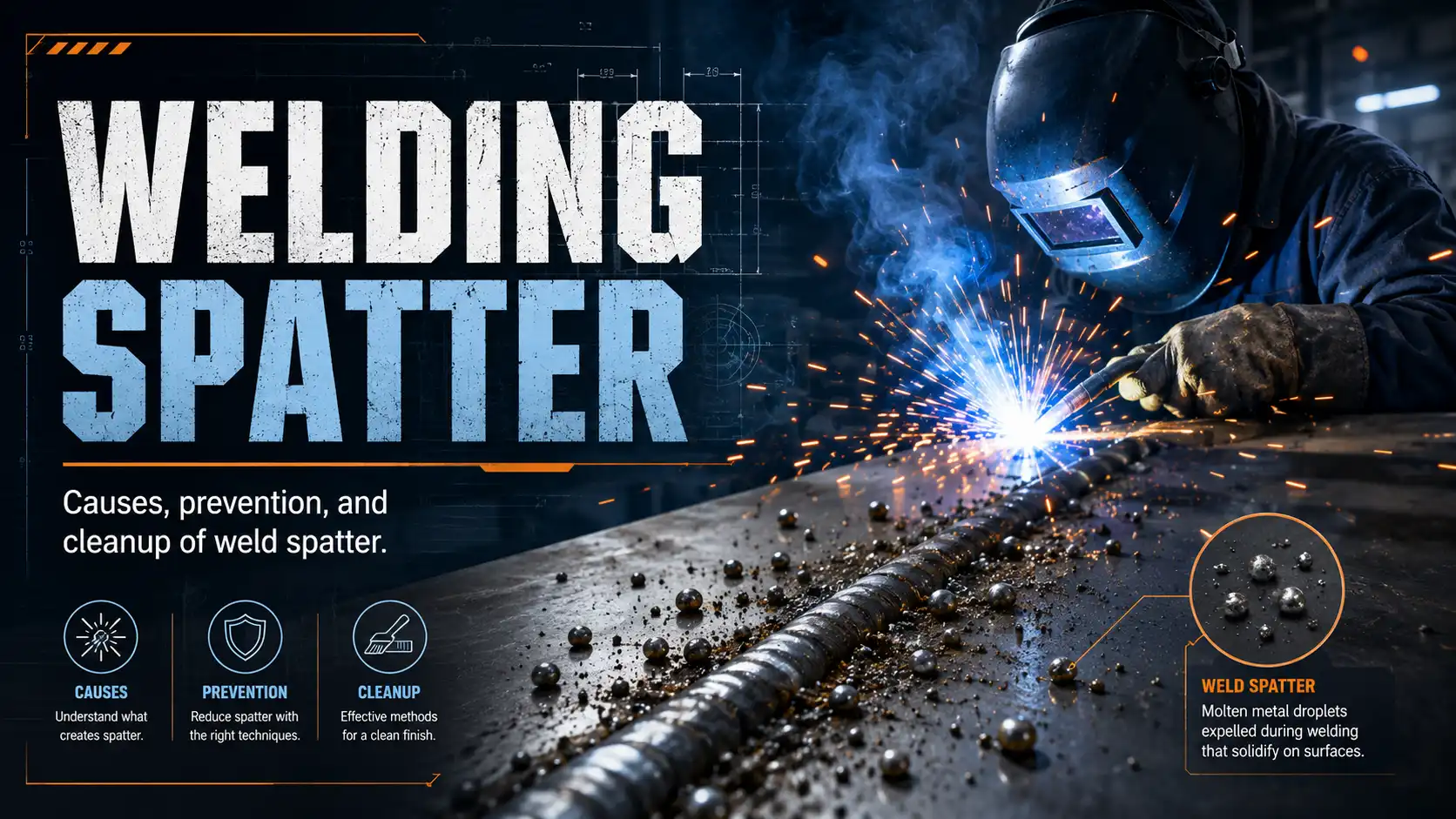
What Welding Spatter Actually Is and Why It Forms
Let’s start with the basics. Welding spatter is essentially what happens when molten metal droplets get ejected from the weld pool or the wire tip during the arc transfer process.
It’s the same liquid steel that should be landing neatly in your joint, but instead, it flies off sideways. So, what causes welding spatter at the physics level?
Well, there are three main mechanisms that do almost all of the damage. Essentially, every parameter problem you might read about later traces back to one of these three.
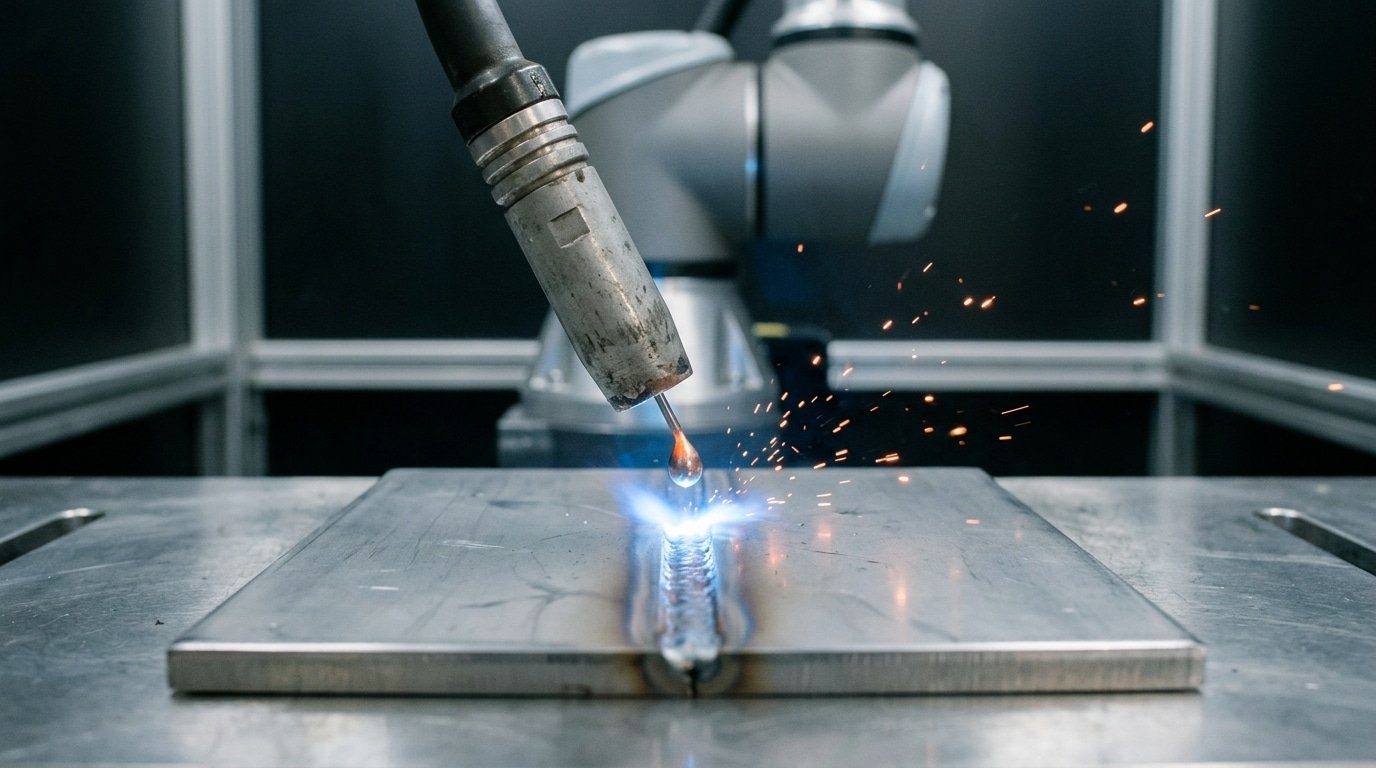
Short-circuit explosions. In short-arc MIG welding, the wire touches the puddle roughly 50,200 times per second. Each contact creates a tiny, fuse-like neck of liquid metal. That neck then ruptures quite violently when the current peaks.
The problem is if the power source can’t taper that current down fast enough. When that happens, the rupture flings droplets outward instead of pinching them cleanly into the pool.
Arc force pressure. This is the electromagnetic force from the plasma column, often called the pinch effect, which pushes down on the droplet. You can read more about it in the AWS literature on GMAW.
If you set the voltage too low, the droplet grows oversized before it detaches. Then, it simply blows apart under that pressure.
Gas turbulence. Shielding gas flow above 35 to 40 CFH becomes turbulent. That turbulence sucks in surrounding air, which oxidizes the droplet surface. And oxidized droplets don’t wet into the pool. They bounce.
Basically, every cause we’ll discuss in the next sections, like voltage settings, contamination, gas mix, or worn tips, disrupts one of these three transfer mechanisms. Fix the transfer, and you kill the spatter.
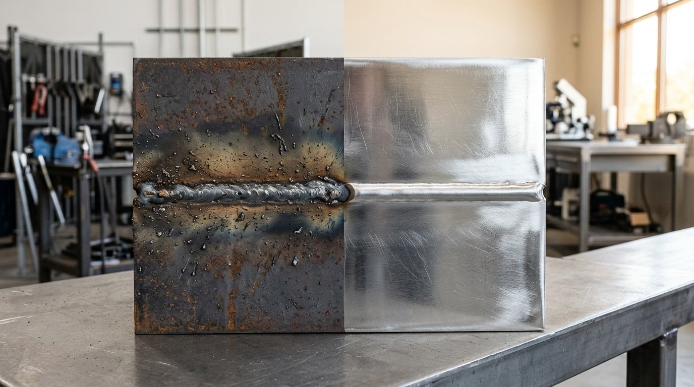
Spatter actually leaves fingerprints behind. Before you go reaching for any dial, take a good look at the bead and the plate around it.
The shape of the droplets and how they’re scattered will tell you exactly what causes welding spatter on that particular joint, and honestly, you can usually figure it out within 30 seconds of just looking.
There are four visual patterns that cover roughly 90%[4] of the field cases documented by the American Welding Society training literature on short-circuit transfer defects:
| Pattern | What You See | Likely Root Cause |
|---|---|---|
| Fine mist | Tiny pinhead-sized specks dusted 2–4 inches around the bead | Voltage cranked too high, so the arc gets too long and the globular transfer ends up breaking apart |
| Large globules | BB-sized droplets welded hard onto the plate | Amperage running too low, or contact-tip-to-work distance pushed over 3/4 inch |
| Sticky adhered droplets | Smeared, oxidized blobs that just refuse to chip off | Mill scale, oil, rust, or the wrong shielding gas being used (pure CO₂ on thin sheet) |
| Explosive scatter | Loud pops, with droplets thrown 12+ inches across the shop | Moisture sitting in the flux or gas, or stickout under 1/4 inch causing tip burnback |
Snap a photo of the pattern with your phone before you start grinding. A quick 10-second image log essentially builds you a personal fault library over time.
After about 20 jobs, you’ll be diagnosing causes faster than you could re-run test beads. The next sections break down each root cause and the parameter fix that actually resolves it.

Cause #1 — Incorrect Voltage and Amperage Settings
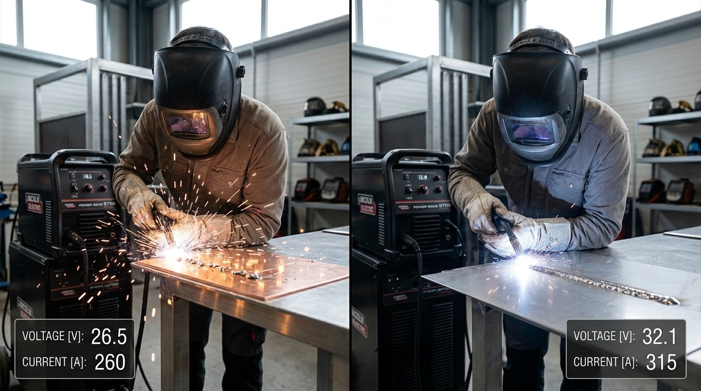
Mismatched voltage and amperage are the single biggest answer to What causes welding spatter in MIG work. When the two dials fight each other, the arc abandons clean spray or short-circuit transfer and falls into Globular transfer, a chaotic mode where oversized molten balls (often 2,3× the wire diameter) detach unpredictably and fling sideways instead of dropping into the puddle.
For approximately 0.035 in[5] (approximately 0.9 mm[6]) ER70S-6 wire on a 90/10 Ar/CO₂ mix, the spray-transfer window sits roughly at approximately 26,29 V[7] and 220,280 A. Drop the voltage to approximately 23 V[8] at the same amperage and you cross the transition current downward, short-circuit fights spray.
And spatter output can roughly double, as documented in the Lincoln Electric procedure handbook.
Short-circuit MIG with the same wire lives lower: approximately 17,20 V[9] at 140,180 A. The trap here is wire-feed speed. Push WFS past 350 ipm without raising voltage and you stub the wire into the plate, each stub blows apart as visible BB-sized spatter.
Practical rule I check on every setup: arc sound. A steady frying-bacon hiss means parameters lock together. A popping, irregular crackle means you’re 1,2 volts off the sweet spot. See the American Welding Society parameter charts for wire-specific windows before tweaking.
Cause #2 — Contaminated Workpieces and Base Metal Issues
Surface contamination is the second biggest reason behind what causes welding spatter, and it explains why so-called “perfect” settings on the machine still throw sparks everywhere. Mill scale, rust, oil, paint, galvanizing, and moisture each mess with the arc in their own way.
Each one leaves a fingerprint on the finished bead too.
How each contaminant misbehaves
- Mill scale is that blue-black iron oxide layer you see on hot-rolled plate straight from the mill. It melts at roughly 2,500°F, which is about 200°F[1] higher than the steel sitting underneath it. The arc punches through this layer unevenly and throws out fine rings of spatter as it does.
- Rust and moisture release hydrogen gas as the arc breaks apart Fe₂O₃·H₂O. That hydrogen creates porosity blowouts. You get loud popping sounds and coarse spatter the size of BBs. Worse, you can end up with cracking under the bead surface in steels above 80 ksi tensile strength.
- Oil, cutting fluid, and paint turn into carbon and hydrocarbon gases when the arc hits them. These gases destabilize the cone of the arc, leaving sticky spatter streaked with smoke residue.
- Galvanizing is honestly the worst offender of the bunch. Zinc boils at approximately 1,665°F[2], which is way below the melting point of steel. Zinc vapor erupts up through the molten puddle as pinhole spatter and leaves behind a porous, gray bead. Both AWS D19.0 and OSHA flag zinc fume as a serious hazard that can cause metal fume fever. See OSHA’s welding hazards guidance for the full picture.
The cleaning standard most articles skip
Grind or wire-wheel the base metal until you see Bright metal at least 1 inch (approximately 25 mm[3]) beyond each side of the joint. Not just the bevel face itself.
AWS D1.1 Clause 5.15 actually requires that surfaces be completely free of scale, rust, moisture, grease, and any other foreign material before you strike an arc.
For galvanized stock, strip the zinc coating back a full 2 inches from the joint. Then weld using straight stringer beads rather than weaving the torch side to side.
That way the zinc vapor has a chance to escape out ahead of the puddle instead of getting trapped inside it.
Cause #3 — Wrong Shielding Gas Mix for the Process
Gas chemistry is really the third honest answer when you’re asking what causes welding spatter. Pure approximately 100%[4] CO2 runs hot and pretty aggressive, producing about 200,approximately 300% more spatter than the argon-rich blends because the CO2 molecule actually breaks apart in the arc, which creates this violent globular kind of metal transfer.
It’s cheap, roughly $0.04[5]/CFH versus approximately $0.09[6] for tri-mix, and that’s basically why production shops still put up with it on heavy structural fillet welds where a bit of spatter doesn’t really matter much.
You really want to match the blend to the way the metal is being transferred:
| Gas Mix | Best For | Spatter Level |
|---|---|---|
| approximately 100%[7] CO2 | Deep-penetration short-circuit on rusty steel | High |
| 75/25 Ar/CO2 | Short-circuit MIG on clean carbon steel | Low-Medium |
| 90/10 Ar/CO2 or tri-mix (Ar/CO2/O2) | Spray and pulse-spray transfer above approximately 24V[8] | Very Low |
And the flow rate matters just as much as the mixture itself. Below 25 CFH the protective gas envelope basically collapses on you.
Above 50 CFH the gas stream actually turns turbulent and creates a kind of suction effect that pulls in atmospheric nitrogen and oxygen from the surrounding air, giving you the same porosity-and-spatter mess you’d get if you had no shielding gas at all.
The American Welding Society generally recommends 35,45 CFH for most 0.035″ wire MIG work.
One thing people often overlook though: a approximately 5 mph[9] crosswind coming from an open bay door or a floor fan will defeat any gas choice you make. If you can feel air moving across your hand at the joint, your shielding is essentially already gone.
Hang up a curtain or just shut the fan off.
Cause #4 — Worn Consumables, Wire Feed Problems, and Liner Issues
So, you have your settings dialed in perfectly, but the arc still pops and sputters. What causes welding spatter in that case?
⚠️ Common mistake: Cranking shielding gas flow above 35 CFH to “better protect” the weld, which actually increases spatter. This happens because excessive flow creates turbulence that pulls atmospheric air into the shielding envelope, contaminating the puddle and triggering droplet ejection. The fix: keep flow between 25-35 CFH and check for drafts instead of boosting gas.
Often, the answer lies with worn replacement parts. The chain of culprits usually runs from the contact tip to the liner to the drive rolls, and each one leaves a different kind of signature on the plate when it fails.
Contact tip wear is a silent killer. What happens is the bore becomes egg-shaped from wire abrasion and arc heat. This makes the electrical current transfer inconsistent, which then causes erratic arc starts and little micro-arcs right inside the tip itself.
You will see scattered, fine spatter and hear a frying sound instead of a steady sizzle. It is important to replace tips on a schedule. Basically, you can follow this rough guide:
- 150–200 A short-circuit MIG: every 30–approximately 40 hours of arc-on time
- 250–350 A spray transfer: every 8–approximately 16 hours[1]
- Pulsed MIG with aluminum: every 4–approximately 8 hours[2] (soft wire wallows the bore fast)
Kinked or coked liners cause the wire to stutter as it feeds. The wire will surge, then stall, then surge again.
And each time it stalls, it dumps a fat blob of spatter because the arc length collapses. You should blow liners out with dry compressed air every time you change the wire spool.
Then you need to replace them every 3 to 6 spools, following Lincoln Electric’s gun maintenance guidance.
Finally, dirty or worn drive rolls will slip under load. This is especially true with knurled rolls that get packed full of copper dust from coated wire.
That slip leads to inconsistent wire speed, which directly causes spatter bursts. You can check the tension with the wire-into-palm test: the wire should bend, not slip.
Cause #5 — Power Source Type and Waveform Control Effects
Your actual machine answers a big chunk of what causes welding spatter. The older transformer-based constant voltage welders, the CV ones, basically dump raw current with no timing on the short circuit, so every single droplet ends up detaching violently.
Modern inverter power sources are a different animal. They use controlled waveforms, pulse, RMD (Regulated Metal Deposition), and STT (Surface Tension Transfer).
They actually sense the short circuit in microseconds and ramp the current down before the droplet snaps free. That one change alone cuts spatter 60,approximately 80%[3] on the same wire and gas.
Here is the mechanism, plain and simple. In standard short-circuit transfer, current spikes up to around 400A the instant the wire touches the puddle. That explodes the bridge and flings metal off sideways.
Lincoln’s STT and Miller’s RMD catch the necking phase and pinch the current back down to roughly 50A. That lets surface tension pull the droplet in cleanly. Synergic pulse modes go even further by firing one droplet per pulse. The detachment is predictable, with almost zero short circuits happening.
So when does upgrading actually beat tweaking? If you have already optimized voltage, gas, contact tip, and drive rolls and you still see heavy spatter on root passes or thin sheet, then honestly the CV machine is your ceiling.
Root passes on pipe and 18-gauge auto body panels are really where waveform control pays back the fastest. Take a look at Lincoln Electric’s STT process documentation for the current waveform diagrams.
Cause #6 — Process-Specific Triggers (MIG, FCAW, Stick, TIG)
Each welding process has one dominant spatter trigger the others don’t share. Generic advice misses these. The honest answer to what causes welding spatter depends on which arc you’re running.
Short-circuit MIG: Inductance setting. Too low and the short clears violently, explosive droplet ejection. Crank inductance up 3,5 clicks and the pinch becomes a controlled fizz. Most shops never touch the dial.
Spray-transfer MIG: Arc length sensitivity. Spray transfer needs roughly 24,29 V[4] on.045″ wire; drop below the transition current (around 220 A for steel per the American Welding Society) and you fall into globular mode, the spatter-heaviest transfer mode that exists.
FCAW: Slag inclusion bursts. When solidified slag from the previous pass gets re-melted, trapped gas erupts as coarse spatter. Chip every restart. Self-shielded FCAW also throws more spatter than gas-shielded, expect it.
Stick (SMAW): Electrode moisture and arc blow. Low-hydrogen rods (E7018) absorb moisture in approximately 4 hours[5] of open air; rebake at approximately 250°F[6] or expect cratering and spatter. Arc blow on DC near plate edges deflects the arc, switch to AC or reposition the ground clamp.
TIG: TIG shouldn’t spatter. If it does, your tungsten touched the puddle or filler, contamination causes a spitting arc. Regrind and restart.
Targeted Fixes Mapped to Each Cause
Match the visual signature to the fix. Don’t guess, read the bead first, then turn one knob at a time. The table below ties together what causes welding spatter and the single corrective action that clears it up fastest in MIG and flux-cored work.
| Visual Signature | Likely Cause | First Fix (try this one change) |
|---|---|---|
| Fine mist, peppered 2–approximately 3 in[7] around bead | Voltage running too high for the speed the wire is feeding | Drop voltage 1–approximately 2 V[8] and keep the wire feed speed exactly where it is |
| Large globules, popping sound, wire stubbing into the plate | Voltage too low, or what welders call a cold short-circuit | Raise wire feed speed by 50 IPM, or shorten the stickout (the wire sticking out of the gun) to 3/approximately 8 in[9] (approximately 10 mm) |
| Sticky droplets welded onto the plate, dull bead | Pure approximately 100%[1] CO2 shielding gas being used on thin steel or dirty mill scale | Switch to a 75/25 Argon/CO2 gas mix and wire-brush the joint clean |
| Erratic spatter bursts, arc length jumps around | Worn-out contact tip or a kinked wire liner inside the gun | Replace the tip. Then blow out the liner with dry compressed air |
| Spatter shows up only at the moment the arc starts | No run-in setting or hot-start control on the machine | Turn on run-in at approximately 70%[2] wire feed speed for 0.3 seconds, or step up to a pulse machine |
Lincoln Electric’s process data backs this up. A properly tuned short-circuit MIG setup keeps spatter loss under 3%[3] of the weight of metal you actually deposit, while mismatched settings throw away 10 to approximately 15%[4].
You can see their transfer-mode charts at the Welding Resource Center. Change one variable at a time, lay down a 4-inch test bead, and then read the pattern again before touching anything else.
Frequently Asked Questions About Welding Spatter
Does anti-spatter spray actually work, or is it marketing?
It really does work, but only as a backup line of defense. Water-based nozzle gels and ceramic-based sprays can cut your cleanup time by roughly 60 to approximately 70%[5] on production fixtures.
But here’s the thing, they don’t actually reduce the amount of spatter itself. They just stop it from sticking to surfaces.
And if you’re spraying down parts to hide what causes welding spatter (things like bad settings or dirty steel), you’re really just masking a deeper process problem. Use the sprays on your jigs, copper backers, and nozzles instead.
Fix the arc first, basically.
Does spatter weaken the weld?
The little spatter droplets themselves don’t actually weaken the bead. They’re metal that got ejected, not metal that’s missing from the joint.
But heavy spatter is generally a sign of an unstable arc, and that often goes hand-in-hand with things like lack of fusion, tiny gas pockets called porosity, and undercut along the edges.
AWS D1.1 treats spatter as more of a cosmetic issue, but inspectors will still flag it because it can hide cracks underneath and create stress concentration points on parts that take repeated loading. You can check out the AWS D1.1 Structural Welding Code for the actual acceptance criteria.
Why does MIG spatter more than TIG?
With MIG, the filler wire is transferred right through the arc itself. In short-circuit and globular modes, the droplets literally explode off the tip of the wire.
TIG works differently, because the filler stays outside the arc. You dip the rod in by hand, so there’s no transfer event happening that could destabilize things.
And that’s really the core reason MIG produces 5 to 20 times more spatter than equivalent TIG work would on the very same joint.
Is pulse MIG worth it for a small shop?
If you regularly weld aluminum, stainless, or thin material under 3 mm[6], then yes, definitely. A pulse-capable inverter runs around $2,500[7] to approximately $4,500.
And it typically lets you make your money back within 12 to 18 months just through the grinding labor you save (about one technician-hour saved per day at approximately $35[8]/hr).
For shops only doing thick mild steel with flux-core wire, just stick with regular CV and skip paying the premium.
Putting It All Together — Your Spatter Reduction Checklist
The diagnostic workflow is four steps, in this order: Observe, identify, fix one variable, verify. Skip a step and you’ll chase ghosts for an hour.
- Observe the pattern. Look at droplet size, distance from the bead, and bead profile before touching any dial. Fine dust at 2 inches is gas. Heavy globs at 6 inches is voltage. Rhythmic clumps every half-second is wire feed.
- Identify the cause from the six categories: parameters, contamination, gas, replacement parts, power source, or process-specific trigger.
- Apply one matched fix. Change a single variable — voltage by approximately 1V[9], gas flow by 5 CFH, or a fresh contact tip. Multiple changes hide which one worked.
- Verify with a 6-inch test bead on scrap of identical thickness. If spatter drops noticeably, lock the setting in your WPS log.
Pre-weld checklist, laminate it and tape it to the welder:
- Wire stickout 3/8″ (approximately 10 mm) for short-circuit MIG
- Gas flow 35–45 CFH, no drafts above approximately 5 mph[1] (per AWS shielding guidance)
- Base metal ground to bright steel within 1″ of the joint
- Contact tip inspected — replace if bore is oval or arcing marks visible
- Voltage and wire speed matched to manufacturer chart for the thickness
- Drive roll tension set so wire slips at a gloved pinch, not before
Bookmark the visual-signature table from Section 9, it answers What causes welding spatter in under 30 seconds at the booth, which on a production line easily saves 20+ minutes of grinding per shift.
References
- [1]denaliweld.com/causes-of-laser-welding-mistakes/
- [2]twi-global.com/technical-knowledge/faqs/what-is-weld-spatter
- [3]tigbrush.com/blog/mig-welding-spatter-causes-and-tips-for-reducing-it/
- [4]blog.binzel-abicor.com/cause-of-weld-spatter-gmaw-welding-and-electric-arc
- [5]twi-global.com
- [6]blog.binzel-abicor.com
- [7]denaliweld.com
- [8]tigbrush.com
- [9]alruqee.com/blog/top-10-causes-of-welding-spatter-ways-to-reduce.aspx
- [10]youtube.com/watch


