

The localized physical result that must meet the product requirement.
Engineering terminology and quality guide
Weld Definition for Industrial Engineers
A weld is the localized joined region produced by a welding process. It is not just the visible bead. In fusion welding, material melts and solidifies; in solid-state welding, a joint can form without bulk melting. The finished weld is acceptable only when it meets the drawing, service, procedure, inspection and acceptance requirements.
The controlled process used to create the weld with heat, pressure or both.
The members, preparation, fit-up and weld or welds at their connection.
A smooth face alone cannot prove fusion, penetration or fitness for service.
Direct answer
What Is the Engineering Definition of a Weld?
A weld is a localized region where materials have joined through a welding operation. Heat, pressure or both can be involved. Filler metal may be added, but it is not required for every weld.
This definition is wider than “melted filler metal.” Arc, laser and electron-beam processes commonly make fusion welds by melting material at the joint. Friction, diffusion and ultrasonic processes can make solid-state welds without melting the base material in bulk.
For an industrial engineer, the word is only the start of the requirement. A critical weld also needs a defined material, joint geometry, process boundary, service duty, inspection plan and acceptance rule. Current terminology is standardized in references such as AWS A3.0M/A3.0:2025 and ISO/TR 25901-1.
Terminology decoder
What Is the Difference Between a Weld, Welding, a Joint, and a Weldment?
Clear terms reduce drawing changes, supplier questions and inspection disputes. These six definitions cover most day-to-day engineering discussions.
The localized joined region produced by welding. It is the result that must satisfy geometry, material and acceptance requirements.
Not: only the top surface you can see.
The process used to create the weld through a controlled combination of energy, pressure, motion, consumables and fit-up.
Not: proof that the result is acceptable.
The members, their joint arrangement and preparation, the fit-up, and one or more welds that connect them.
Not: a synonym for one bead.
A component or subassembly that contains welded joints. Distortion, residual stress, dimensions and finishing often matter at this level.
Not: only a procedure coupon.
The result of one weld pass, often visible as a run on the surface. A multi-pass weld contains more than one bead.
Not: proof of the internal condition.
In a fusion weld, the material that melted and solidified. Its chemistry can include base-metal dilution and added filler metal.
Not: automatically identical to the base material.

Process versus result
The operator performs welding. The joined region left behind is the weld.In this gas metal arc welding example, the power source, wire electrode, shielding gas, torch motion and operator technique are parts of the welding process. The bead and joined region produced on the workpiece are parts of the weld. Industrial records should identify both: how the result was made and whether that result met the released requirement.
Photo: William M. Plate Jr., U.S. Air Force, Wikimedia Commons, public domain in the United States.How joining happens
How Do Fusion Welding, Solid-State Welding, and Brazing Differ?
The mechanism changes the variables that production must control. It also explains why neither melting nor filler wire belongs in every valid weld definition.
Fusion welding
Arc, laser and electron-beam processes commonly create a molten zone that solidifies. Filler may be added or the joint may be autogenous.
- Control energy, travel, shielding, focus or arc, filler and cooling.
- Check fusion boundary, root condition, porosity, cracking and profile.
Solid-state welding
Friction, diffusion, ultrasonic and related processes form coalescence through pressure, deformation, motion and heat without bulk melting.
- Control force, displacement, time, interface condition, tooling and alignment.
- Evaluate bonded area, upset, flash, interface and service performance.
Brazing and soldering
A lower-melting filler flows while the base materials remain solid. These processes can be excellent choices, but the joint-clearance and acceptance logic differs.
- Name the actual joining method in drawings and records.
- Do not call brazing “low-temperature welding.”
Laser-welding connection: Laser beam welding is normally a fusion process. It may use conduction or keyhole mode and may be autogenous or wire-fed. A focused beam can create a narrow fusion zone, but the result still depends on material, fit-up, surface condition, focus, speed, shielding, clamping and the approved acceptance criteria. See the laser welding working principle for the process-level explanation.
Inside a fusion weld
What Parts Make Up a Fusion Weld?
A cross-section makes the definition practical. It shows why surface appearance cannot prove the root, fusion boundary or heat-affected material.
Material that melted and solidified. Chemistry, dilution and solidification can affect strength, toughness, corrosion and cracking.
The interface between melted weld metal and unmelted base material. Incomplete fusion can occur along this boundary.
Base material that did not melt but changed because of heat. The HAZ is expected, not automatically defective. Read the laser-welding HAZ guide.
The root is the deepest region, the toes meet the base material at the face, and the face is the exposed surface. Learn why weld-toe position matters.

Evidence below the surface
A polished macrosection can reveal what the bead cannot.During procedure development, a sectioned coupon can show fusion, penetration, root condition and major internal features at the cut plane. It is destructive and local, so it does not prove every point of a production weld. The sampling plan and acceptance criteria still need to match the product risk.
For more detail, see what weld penetration means and how root gap affects welding quality.
Photo: Alu.cz, Wikimedia Commons, public domain.Geometry before process
How Does Joint Type Affect the Weld Requirement?
A joint describes how parts meet. A weld type describes the joined or deposited geometry used at that meeting. One joint type can support several weld types and processes.
Members generally align in one plane. Groove, square or other weld details may be used.
One member overlaps another. Access, load direction and corrosion traps need attention.
One member meets another near a right angle. Fillet and groove details are both possible.
Members meet at a corner. Sheet-metal fit-up, cosmetics and distortion often control the detail.
Adjacent edges are joined. Loading, thickness and access determine whether it is suitable.
Drawing rule
Do not specify only “fillet weld” or “laser weld” when size, length, side, contour, root condition, access or inspection affects performance. A weld symbol is a communication tool, not the complete manufacturing plan. Use the welding-symbol visual guide when reviewing drawing callouts.
Process-family comparison
How Do Common Welding Process Families Differ?
Choose a process from the joint and production requirement—not from a generic belief that one process is always stronger or faster.
| Process family | How the joint forms | Frequent advantage | Important constraint |
|---|---|---|---|
| Arc welding | An electric arc forms a fusion weld; filler and shielding depend on the process. | Versatile across many fabrication geometries. | Heat input, access, consumables, shielding, distortion and operator or automation control. |
| Resistance welding | Electrical resistance heating plus force forms a localized joint, often a nugget in overlapping sheet. | Fast, repeatable joining for suitable sheet assemblies. | Electrode condition, force, current, coatings, stack-up and two-sided access. |
| Laser beam welding | A focused beam creates a local fusion zone; filler can be omitted or added. | Localized energy, high travel potential and automation compatibility for controlled joints. | Fit-up, surface condition, reflectivity, focus, shielding, fixture stability and Class 4 safety controls. |
| Electron-beam welding | A focused electron beam creates a fusion zone, commonly in a controlled environment. | Deep, narrow weld potential for specialized applications. | Equipment, chamber or vacuum needs, access and production complexity. |
| Solid-state welding | Pressure, motion, deformation and heat join surfaces without bulk melting. | Can avoid some fusion-solidification problems for suitable material pairs. | Tooling, interface preparation, force/displacement control, flash and alignment. |
This table describes families, not qualified settings. Actual material and product requirements control process selection.
What “good” means
What Makes a Weld Acceptable?
A cosmetic cover, pressure boundary, fatigue-loaded frame and battery interconnect do not share one universal checklist. The evidence must connect the welded joint to what the product needs to survive.
When Does an Imperfection Become a Defect?
A discontinuity becomes rejectable when it fails the governing acceptance criteria. Identify and measure the condition before calling it a defect. Cracks are normally unacceptable, but the applicable fabrication code remains the authority.
Define the functional duty
Load, fatigue, pressure or leak, vibration, corrosion, temperature, electrical resistance, cleanliness, dimensions and appearance.
Release the joint requirement
Materials, thickness, joint arrangement, weld size or penetration, side, length, contour, fit-up and post-weld condition.
Control the production procedure
A WPS or controlled work instruction defines the variables needed to make the weld repeatably within its approved range.
Confirm capability and personnel
Procedure qualification evidence and welder or operator qualification answer different questions. One does not automatically replace the other.
Inspect with the right method
Visual, dimensional, destructive, NDT, leak, electrical or functional tests are selected for the condition and service risk.
Compare with the acceptance rule
The method finds or measures a condition. The code, customer specification or engineered acceptance criteria decide whether it passes.
Inspection is not acceptance
Which Inspection Method Fits the Weld Risk?
“100% NDT” is still incomplete if the RFQ does not state the method, extent, timing, report and acceptance basis.
Visual, dimensional, PT and MT
Visual testing can be used before and after welding. It can examine fit-up, profile, undercut, surface cracks and visible workmanship. Liquid penetrant finds surface-breaking conditions on suitable nonporous materials. Magnetic particle testing applies to ferromagnetic materials.
- State viewing conditions and measurement tools.
- Define which surfaces and stages are examined.
- Do not use a surface method to claim internal soundness.
UT, RT, leak and performance tests
Ultrasonic and radiographic techniques can examine certain internal conditions. Leak tests address containment. Electrical, pull, bend, fatigue or other functional tests may be more relevant for a specific product.
- Geometry and material affect method capability.
- An indication still needs interpretation and acceptance criteria.
- Sampling should reflect service risk and production control.

Quality evidence
NDT can examine a weld without cutting the finished part apart.It is not a universal window into every discontinuity. Technique, coverage, calibration, material, geometry and acceptance standard must be defined. For laser production, a smooth top bead still does not prove the required fusion or root condition. The laser-welding seam quality checks provide a practical starting point, not a substitute for the governing code.
Photo: Davidmack, Wikimedia Commons, public domain.Drawing to acceptance
Which Documents Define and Control a Weld?
A weld requirement moves through six different documents and decisions. Keeping their roles separate makes supplier discussions clearer: a symbol cannot replace a WPS, and a procedure cannot define the product’s load path.
What the joint must carry, contain, conduct, resist or look like.
Where the weld is, its type, dimensions, extent and referenced requirements.
The controlled production variables used to make the weld repeatably.
Evidence for procedure capability and for the welder or operator, when required.
Traceability, actual settings, material, consumables, inspection and deviations.
Measured results compared with the applicable contract or code criteria.
Answers: “How should production make the weld within an allowed range?” It does not, by itself, prove that a new procedure is qualified.
Records the actual qualification test conditions and results supporting a procedure under the chosen system.
Shows that the person or system operator can work within an approved range. It is separate from procedure qualification.
Beam-welding boundary: Do not assume an arc-welding quality document covers laser welding. ISO 15614-11:2025 addresses procedure qualification testing for electron and laser beam welding. ISO 5817:2023 explicitly excludes beam welding; applicable laser/electron-beam imperfection levels are covered by ISO 13919-1 and ISO 13919-2.
One definition, different duties
How Does an Acceptable Weld Change by Application?
These three scenarios show why a generic “strong, neat weld” note does not give production enough information.
The priority may be low distortion, a closed corner, controlled cosmetics and a corrosion-resistant post-weld finish.
- Define visible and hidden faces.
- State distortion and blending limits.
- Specify cleaning or passivation.
- Confirm whether a continuous seal is needed.
The priority may be electrical resistance, controlled heat near cells, pull or shear strength and consistent penetration.
- Define material stack and plating.
- Control clamping and deformation.
- Choose electrical or mechanical verification.
- Do not judge from bead width alone.
The priority may be load path, fatigue, access, drainage and corrosion protection across the whole weldment.
- Connect weld detail to structural duty.
- Avoid water-trapping profiles.
- Repair coating over welds and cut edges.
- Inspect after the relevant finishing stage.
Interactive planning aid
What Should a Buyer Put in a Welding RFQ?
Tick the information already controlled. The result shows which gaps are most likely to create assumptions, change orders or incomparable quotations.
Check your RFQ scope
Use released information, not verbal expectations. This check does not approve a design or procedure.
RFQ completenessStart with the product duty.
Before naming a welding process, define the parts, the joint and what the completed assembly must do.
- Seven requirement groups are still missing.
Planning aid only. The governing drawing, code, customer specification and qualified welding authority control the final requirement.
Common engineering mistakes
Which Weld-Definition Mistakes Create Production Risk?
Brazed, soldered, bonded and mechanically fastened joints can need different clearance, inspection and compliance controls.
Better: name the actual joining process and joint requirement.
The process name does not state required size, penetration, leak behavior, fatigue duty or inspection scope.
Better: define function, geometry, procedure boundary and acceptance.
A neat face can hide incomplete fusion, porosity, an incorrect root condition or an unqualified procedure.
Better: use visual inspection as one part of risk-based evidence.
Penetration is one condition. Extra heat, preparation, distortion, inspection and cost may add no value when the load path does not need it.
Better: specify only the penetration condition required by the design.
These phrases do not define which discontinuities, method, coverage, timing or acceptance rules apply.
Better: state method, extent, reporting and acceptance source.
A qualified welder does not automatically qualify a new procedure, and a qualified procedure does not qualify every welder or operator.
Better: review each required evidence package separately.
Continue the engineering path
What Should You Read Next?
Quick answers
Frequently Asked Questions About Weld Definitions
Short answers to the questions engineers and buyers ask most often.
What is the simplest definition of a weld?
A weld is the localized region where materials have joined through welding. In fusion welding, material melts and solidifies. In solid-state welding, the joint can form without bulk melting. The term describes the joined result, not only the visible bead.
Is welding the same as a weld?
No. Welding is the process or operation used to join materials. A weld is the joined region produced by that operation. A process may be approved, but each resulting weld still must meet its geometry and acceptance requirements.
What is the difference between a weld and a welded joint?
A weld is the localized joined zone. A welded joint includes the parts, their fit-up and geometry, and the weld or welds that connect them. One joint may include several passes, sides or welds.
What is a heat-affected zone?
The HAZ is base material next to a thermal welding operation that did not melt but changed in microstructure or properties because of heat. It is expected, not automatically defective. Its importance depends on the material and service.
Can a good-looking weld still fail inspection?
Yes. Surface appearance cannot prove every internal condition, root condition, material property, leak requirement or procedure qualification. Use the inspection method and acceptance criteria required by the product risk and governing specification.
What welding documents should a buyer request?
Depending on risk and contract, ask for the released drawing, material traceability, applicable WPS, procedure qualification evidence, welder or operator qualification, inspection plan, inspection records, deviation approvals and fabrication traceability.
References and standards
Sources and Technical Review
Standards define terminology and contractual frameworks. Always use the edition named by the governing drawing, code or customer specification.
- AWS A3.0M/A3.0:2025 — Standard Welding Terms and Definitions.
- AWS SCC1.0:2026 — public safety and health terminology glossary.
- ISO/TR 25901-1:2016 — general welding vocabulary.
- ISO 4063:2023 — welding and allied-process nomenclature and reference numbers.
- ISO 2553:2019 and AWS A2.4:2020 — symbolic representation on drawings.
- ISO 15607:2019 — general rules for welding procedure specification and qualification.
- ISO 15614-11:2025 — procedure qualification for electron and laser beam welding.
- ISO 17635:2025 and ISO 17637:2016 — NDT selection and visual testing.
- ISO 5817:2023 — imperfection quality levels for its stated fusion-welding scope; excludes beam welding.
- ISO 13919-1:2019 and ISO 13919-2:2021 — quality levels for applicable electron- and laser-beam-welded joints.
- NIST Welding Data Dictionary — separates joint, weld, procedure, fabrication and inspection data entities.
- OSHA welding hazards and FDA laser hazard classes — process and Class 4 laser-safety context.
Image credits
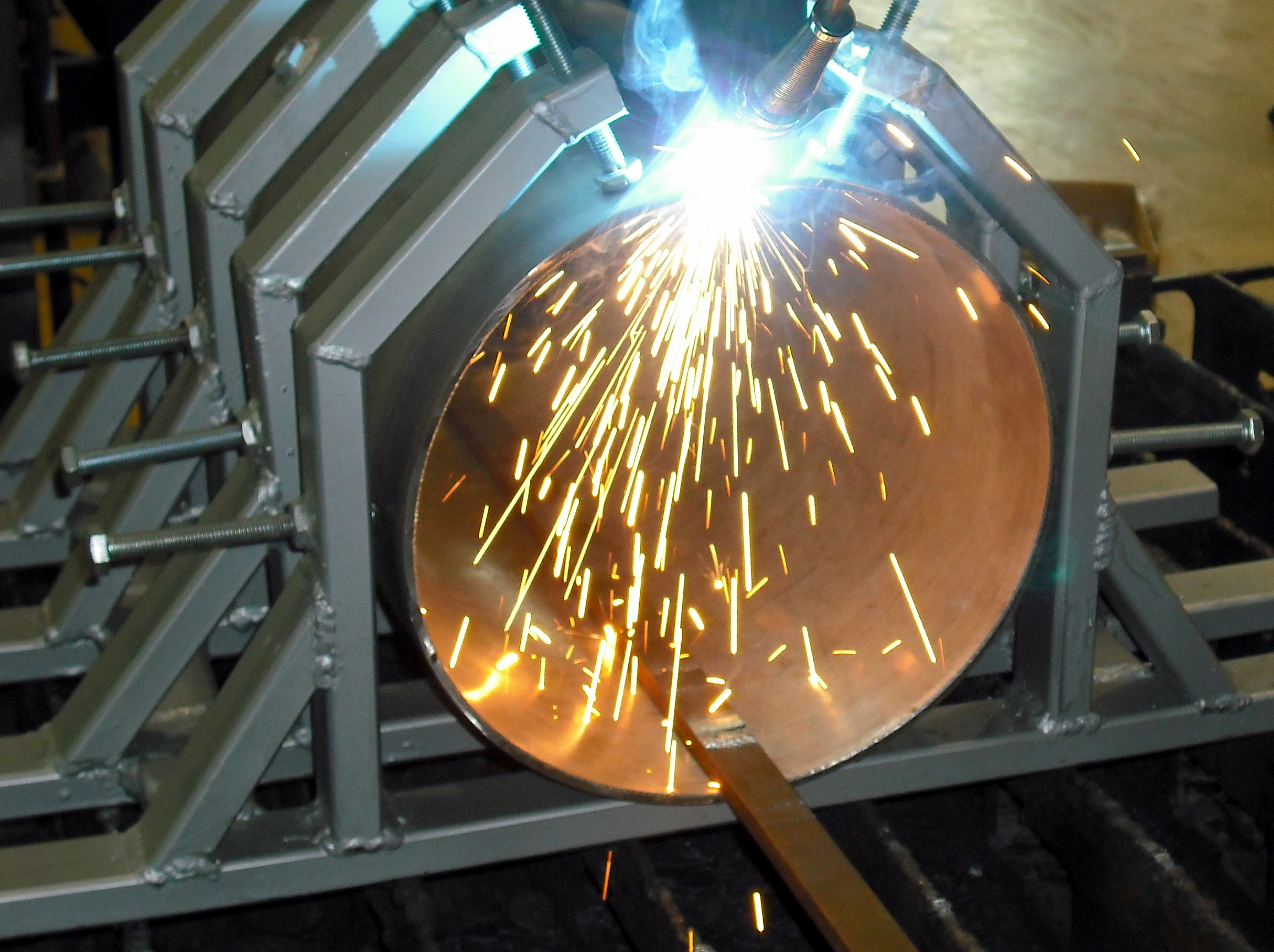
Hero: “Laser welding of the pipeline,” Barbara Nasiłowska, CC BY 4.0. GMAW operation: William M. Plate Jr., U.S. Air Force, public domain in the United States. Macrosection: “V-butt-weld,” Alu.cz, public domain. Ultrasonic inspection: “Ultrasonic pipeline test,” Davidmack, public domain. Source pages are linked with each image.
From definition to production trial
Get a Welding Recommendation Based on Your Joint
Oceanplayer Laser can review whether handheld or automated laser welding is a practical production route. A useful review starts with evidence, not only a photo of the bead.
- Material grades, condition and thickness
- Joint drawing, fit-up and access
- Service and acceptance requirements
- Current process and problem
- Prototype, batch and annual volume