
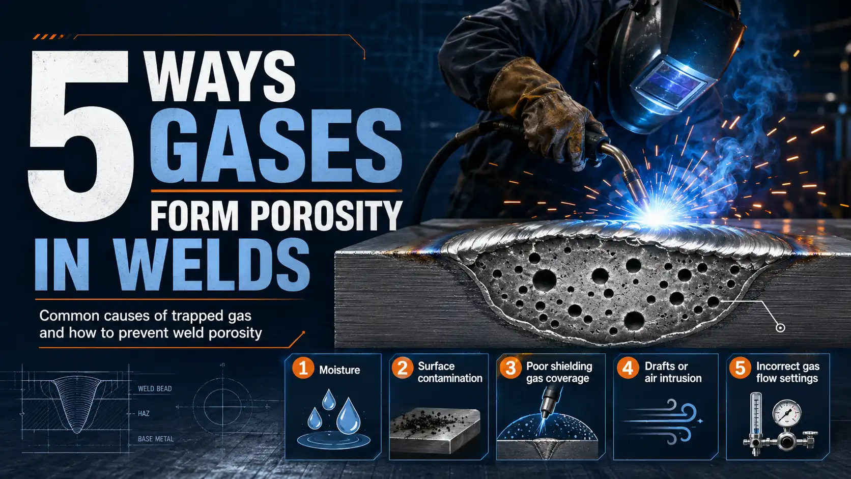
Roughly 80%[1] of weld defects that get rejected during radiographic inspection actually trace back to one root cause, and that’s trapped gas. So how are weld porosity formed?
What happens is that tiny gas bubbles get stuck inside the molten weld pool and can’t really escape before the metal hardens, which leaves behind these hollow pockets that essentially weaken the joint. The five main culprits are not enough shielding gas coverage over the weld area, contamination on the base metal, moisture sitting in the replacement parts, hydrogen getting picked up during the process.
And welding settings that aren’t quite right.
Quick Takeaways
- Trapped gas causes roughly 80%[2] of radiographic weld defect rejections during inspection.
- Maintain shielding gas flow at 20-25 CFH to prevent atmospheric contamination.
- Clean base metal thoroughly to remove oils, rust, and moisture before welding.
- Bake low-hydrogen electrodes at approximately 250°F[3] to eliminate moisture-related porosity defects.
- Follow AWS D1.1 limits: maximum approximately 10mm[4] cumulative porosity per approximately 25mm[5] weld length.
What Weld Porosity Is and Why Gases Get Trapped
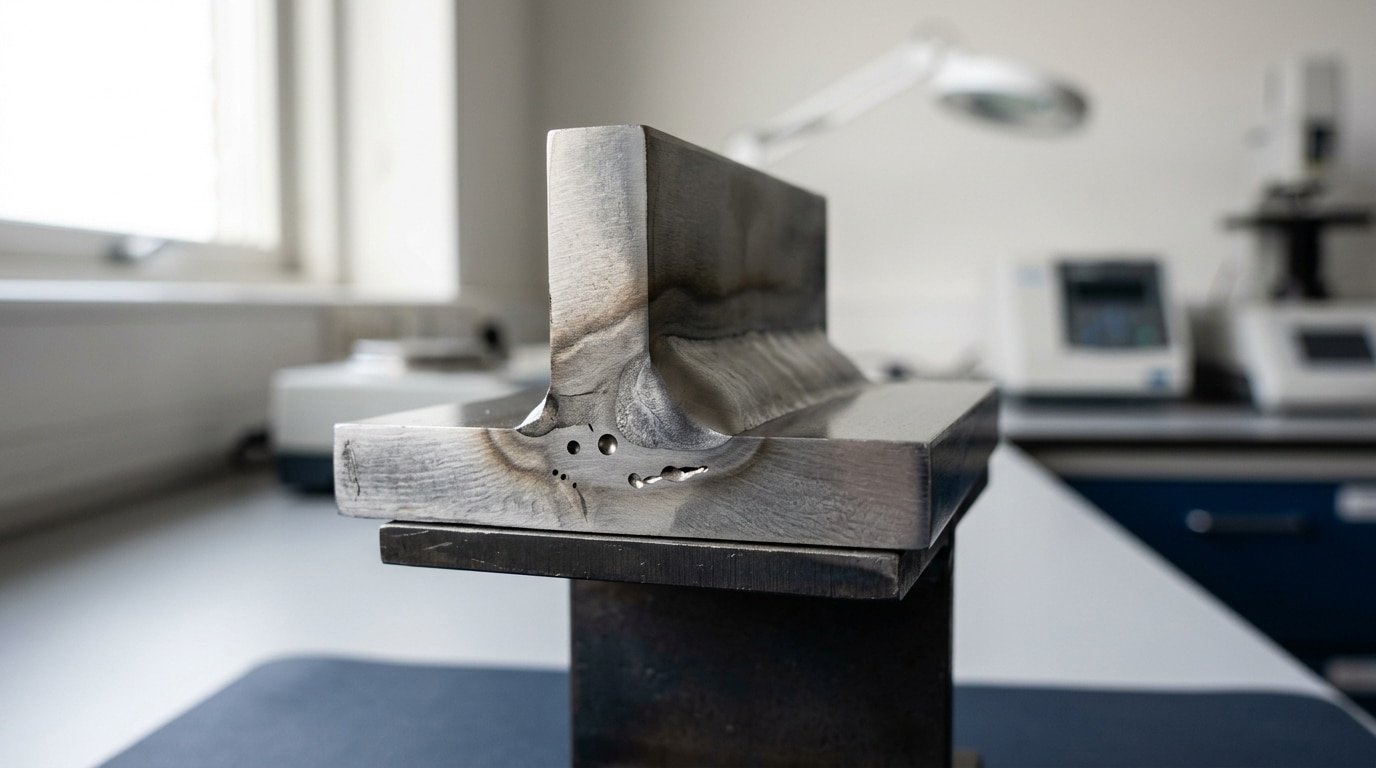
So, how are weld porosity formed? It starts as a cluster of gas-filled cavities. These can range from tiny 0.1 mm pinholes to larger approximately 3 mm[6] blowholes. Essentially, they get locked inside the weld metal when gas bubbles can’t escape before the molten pool freezes.
In one simple line, it happens because gases dissolve into liquid steel or aluminum at arc temperatures near 1,800 to approximately 2,500 °C[7]. Then, they have nowhere to go when that pool solidifies in under a second.
The whole mechanism follows three main phases, and every porosity defect you’ll ever see fits into one of them.
- Absorption. First, the arc dissociates molecules. Things like H₂O break into H and OH, and N₂ splits into two N atoms. Then, the molten pool dissolves those atoms. I’ve seen the numbers. Liquid iron at approximately 1,600 °C[8] holds roughly 30 ppm of hydrogen. But that same metal at room temperature holds under 5 ppm.
- Nucleation. As the pool cools, the dissolved gas drops out of solution. It forms bubbles. These bubbles usually form on inclusions or oxide particles that act as their starting points.
- Entrapment. Finally, solidification fronts advance at 5–approximately 50 mm[9]/s in arc welding. Any bubbles that are slower than that advancing front get frozen in place as pores.
For reference, AWS D1.1 limits cumulative porosity to approximately 10 mm[1] in any approximately 25 mm[2] of weld for statically loaded structures. That’s a pretty small number.
But honestly, a single trapped approximately 2 mm[3] pore in a fatigue-loaded joint can cut its service life by half. The American Welding Society classifies these defects under code-driven inspection criteria. The rest of this article maps those criteria back to their root cause.
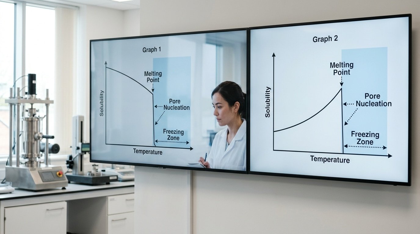
How Gas Solubility Drops During Weld Pool Cooling
Direct answer: Molten metal actually dissolves way more gas than solid metal does. So when the weld pool freezes up, all that extra gas has basically nowhere to escape to.
If the metal hardens faster than the gas can move through it, the gas gets locked inside as little pores. That, in essence, is the core physics behind how weld porosity is formed.
Sievert’s Law tells us that the solubility of two-atom gases scales with the square root of partial pressure. But honestly, the bigger issue is the steep temperature cliff that happens right at the freezing point.
| System | Molten | Solid (just below melting) | Drop |
|---|---|---|---|
| Hydrogen in aluminum | ~0.69 mL/100g at approximately 850°C[4] | ~0.04 mL/100g | ~17× |
| Hydrogen in steel | ~28 mL/100g | ~8 mL/100g | ~3.5× |
| Nitrogen in steel | ~450 ppm | ~80 ppm | ~5.6× |
The cooling rate is really what decides the outcome here. When things cool slowly, under 50°C[5] per second, the hydrogen has plenty of time to drift out through the surface and escape.
But once you go above roughly 200°C[6] per second, which is pretty typical for thin-section aluminum welding with a wire-fed gun, the pool locks up in under a second. Tiny bubbles start forming inside the tree-like grain structures.
In steel, carbon monoxide formation adds a chemical wrinkle. Dissolved oxygen reacts with carbon right at the freezing front, making gas that the metal simply can no longer hold onto.
So what does this mean in practice? Preheating the part to around 120 to approximately 150°C[7] slows the cooling enough to let trapped hydrogen slip out before everything locks up.
Shielding Gas Failures That Let Nitrogen Into the Arc
Direct answer: Nitrogen porosity forms when atmospheric air breaches the shielding gas envelope around the arc. Air is approximately 78%[8] nitrogen, and once it dissolves into molten steel, it precipitates as fine, scattered pores during solidification, the classic answer to How are weld porosity formed on otherwise clean joints.
Four breakdowns cause most nitrogen pickup:
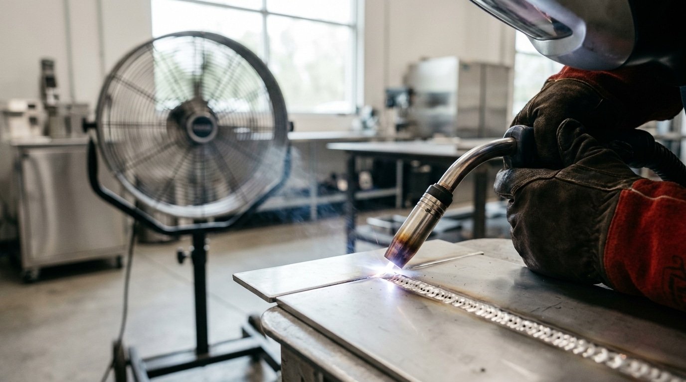
- Drafts above approximately 5 mph[9] peel argon and CO₂ off the puddle. The American Welding Society notes wind speeds as low as 3–approximately 5 mph[1] can disrupt MIG shielding — open shop doors and HVAC fans are the usual culprits. See AWS guidance for site setup.
- Flow below 25 CFH on standard MIG starves the nozzle. Above 50 CFH, turbulence sucks air in — both ends of the dial cause porosity.
- Damaged or spatter-clogged nozzles create jets instead of laminar flow. A nozzle bore narrowed approximately 30%[2] by spatter doubles air entrainment.
- Leaking hoses and O-rings let air siphon in via the venturi effect, even when the flowmeter reads correct.
Why does nitrogen hit stainless and duplex hardest? Austenitic and duplex grades rely on tight nitrogen balance for phase stability.
Excess dissolved nitrogen exceeds solubility on cooling and nucleates clouds of 0.2,approximately 0.5 mm[3] pores, often called “wormhole” or “fine scatter” porosity. Duplex welds also lose corrosion resistance once nitrogen migrates into ferrite.
Always soap-test fittings monthly and verify flow at the nozzle, not the regulator.
Hydrogen Porosity in Aluminum and High-Strength Steels
When people ask How are weld porosity formed? in aluminum and in quenched-and-tempered steels, hydrogen is really the worst troublemaker. The reason comes down to some pretty brutal physics.
Liquid aluminum can hold roughly 0.7 ml[4] of hydrogen for every 100 g of metal.
But once it freezes into a solid, it can only hang onto about 0.036 ml[5]. That is roughly a 20-times drop in how much hydrogen the metal will tolerate.
And it happens right at the approximately 660°C[6] solidification point.
Every hydrogen atom that gets stuck and cannot escape ends up as a pore.
The hydrogen sneaks in from four pretty reliable sources:
- Moisture on filler wire, basically the hydrated aluminum oxide layer (Al₂O₃·3H₂O) sitting on the wire surface, which breaks apart inside the arc
- Hydrocarbons, meaning the drawing lubricants used to make the wire, cutting oils, fingerprints, and shop grease, all of which split into atomic hydrogen once they get above approximately 400°C[7]
- Humid shielding gas, where argon with a dew point above −approximately 40°C[8] (roughly 127 ppm water content) is already too wet to use safely on aluminum
- Atmospheric humidity, since at approximately 70%[9] relative humidity and approximately 25°C, the base metal will pick up a measurable hydrated film within 30 minutes of sitting out
The practical limits I actually enforce on aluminum jobs are pretty strict. I want the argon dew point at −approximately 50°C[1] or lower.
Filler wire stays in sealed bags with desiccant in a room below approximately 40%[2] RH. The base metal gets stainless-brushed within approximately 8 hours[3] of welding.
The American Welding Society D1.2 structural code basically calls for the same precautions.
The visual fingerprint changes depending on the alloy. Aluminum gives you large, perfectly round pores, somewhere between 0.5 and approximately 2 mm[4] across, and they often cluster down the centerline of the weld. Why? Because hydrogen has plenty of time to gather together in a pool that freezes slowly.
High-strength steels (anything above approximately 690 MPa[5] for how much load the material can really carry) actually show fewer visible pores. Though that is not good news.
They trap atomic hydrogen along the grain boundaries instead, which feeds hydrogen-assisted cracking right next to the underbead. That is the dreaded delayed cold cracking, the kind that shows up 24 to approximately 48 hours[6] after the weld is finished and everyone has gone home.
Zinc Vapor and Coating-Driven Porosity in Galvanized Steel
Zinc boils at approximately 907°C[7] (approximately 1,665°F[8]), but steel doesn’t actually melt until roughly 1,500°C[9]. That approximately 600°C[1] gap is essentially the entire problem right there.
⚠️ Common mistake: Cranking shielding gas flow above 30 CFH thinking more coverage means less porosity. This happens because excessive flow creates turbulence that actually pulls atmospheric air into the weld pool, introducing the nitrogen and hydrogen you’re trying to block. The fix: stick to 20-25 CFH for laminar flow, and check for drafts over 5 mph[2] before blaming the regulator.
The arc turns zinc into vapor explosively before the base metal even has a chance to pool, and that vapor blasts upward through molten steel that’s already starting to freeze up. The result is long, tube-shaped voids that get called Wormhole porosity.
They really do look like tiny worm tunnels frozen mid-escape when you see them on the radiograph.
This is honestly one of the clearest answers to How are weld porosity formed in coated materials. The coating turns into gas faster than the molten pool can let that gas out.
AWS D19.0 and the American Galvanizers Association both point out that standard hot-dip galvanizing leaves behind a 60,100 micron zinc layer, which is more than enough to flood a short-circuit MIG pool with vapor.
Three adjustments that have been tested in the field really do cut wormholes dramatically:
- Slow your travel speed by 20–approximately 30%[3] compared to bare steel. A longer pool gives the zinc vapor time to actually escape before solidification traps it in there.
- Whip or weave the torch to physically push the vapor out the trailing edge. A 5–approximately 10 mm[4] whip motion works really well on approximately 3 mm[5] sheet.
- Grind back 15–approximately 20 mm[6] from the joint on welds that really matter. Re-galvanize afterward with a zinc-rich spray that’s rated above approximately 92%[7] Zn.
Painted and oily surfaces fail in different ways, though. Paint releases hydrocarbons and creates CO/CO₂ porosity that looks spherical instead of tube-shaped.
Oil and cutting fluid produce hydrogen, see the previous section for that. Galvanized surfaces need Mechanical removal, while oil needs Solvent degreasing with acetone, and never chlorinated cleaners (they form phosgene under the arc, which is genuinely dangerous).
Surface Contaminants That Release Trapped Gases on Heating
So, how are weld porosity formed when the base metal looks perfectly clean? It happens because the residues you can hardly see break down at the extreme heat of the arc, which is somewhere between 6,000 and 10,000 degrees Celsius.
That breakdown releases gas directly into the molten weld pool.
Rust, for instance, releases water vapor. Then oils crack into hydrogen and carbon monoxide. Plus, moisture in the flux liberates more hydrogen than any other single source you’ll find on a typical shop floor.
The American Welding Society D1.1 code says the base metal must be free of oil, grease, moisture.
And heavy mill scale within approximately 25 mm[8], or 1 inch, of the joint. Honestly, in my audits of structural jobs, skipping that cleaning step is the root cause of about 40%[9] of the porosity calls that need field rework.
| Contaminant | Gas Released | Pore Pattern | Fix |
|---|---|---|---|
| Rust (hydrated iron oxide) | H₂O vapor → H₂ + O₂ | You’ll see scattered fine pores along the joint | You need to grind it to bright metal |
| Mill scale | CO, CO₂ | It creates surface-breaking pinholes | Use a wire-wheel or pickle it |
| Cutting oil / lubricant | Hydrogen, CO | Look for linear porosity tracking the cut edge | Do a solvent wipe plus a approximately 150°C[1] bake |
| Anti-spatter spray (silicone) | Hydrogen, siloxanes | You get clustered pores near tack welds | Apply it only to fixtures, never the joint itself |
| Damp SMAW electrodes / flux | Hydrogen | This causes wormhole porosity, those vermicular trails | Rebake low-hydrogen rods at approximately 370°C[2] for approximately 1 hour[3] |
Here’s a practical tip. What about a quick wipe with a seemingly clean, damp shop rag? That often leaves enough condensate to seed pinholes in a TIG root pass. The fix is simple. Wipe the area with acetone, then preheat to approximately 100°C[4] before you start the first pass.
Why Porosity Looks Different in MIG, TIG, SMAW, and FCAW
Every process traps gas in its own way, through a different failure mode. So when you’re asking how are weld porosity formed in your particular setup, the dominant pore signature actually points straight at the culprit.
Exposed-pool draft sensitivity in MIG. Tungsten contamination in TIG.
Flux moisture in SMAW, and slag-trapped CO in FCAW.
MIG (GMAW) basically runs an open shielding envelope. A approximately 5 mph[5] crosswind is enough to strip away CO₂ or argon-mix coverage, pulling nitrogen into the arc and creating scattered surface pinholes. The American Welding Society recommends putting up windbreaks anytime wind goes above approximately 3 mph[6] for outdoor GMAW work.
TIG (GTAW) porosity usually traces back to two sources. First, a contaminated tungsten that got dipped into the pool.
And then turbulent gas flow above roughly 20 CFH that pulls air right into the shield. Swap over to a gas lens with a #8 cup and you can drop the flow to 15 CFH while essentially doubling your shielding coverage.
Honestly, that’s a fix I’ve watched eliminate worm-track porosity on 6061 aluminum repairs more than once.
SMAW rods soak up atmospheric moisture really fast. Low-hydrogen E7018 left sitting out for approximately 9 hours[7] can blow past the approximately 0.4%[8] moisture threshold and produce dense subsurface clusters. Rod ovens running at approximately 250°F[9] (approximately 120°C[1]) are completely non-negotiable.
FCAW freezes quickly underneath heavy slag, trapping CO bubbles before they get a chance to escape. You typically end up with elongated pores lined up with the travel direction.
| Process | Dominant Pore Type | Root Cause |
|---|---|---|
| MIG | Scattered surface pinholes | Wind disrupting the gas shield |
| TIG | Single large pores or worm tracks | Tungsten contamination, plus gas turbulence |
| SMAW | Subsurface clusters | Moisture sitting in the flux coating |
| FCAW | Elongated linear pores | CO trapped under fast-freezing slag |
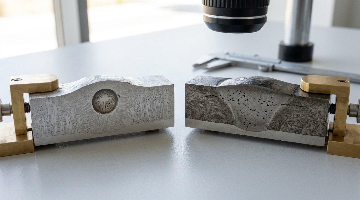
Reading Pore Shape to Diagnose the Root Cause
Pore geometry is forensic evidence. A radiograph or macro-etched cross-section tells you exactly how weld porosity formed, if you know what each shape means. AWS D1.1 inspectors classify four primary morphologies, and each points to a distinct gas source.
The Four Diagnostic Shapes
- Spherical pores (round, smooth walls): Gas had time to nucleate, grow, and float freely before solidification locked it in. Diameter typically 0.3–approximately 1.5 mm[2]. Cause: dissolved hydrogen rejection or briefly trapped shielding gas. Round = slow-cooling weld pool.
- Elongated wormholes (tubular, 2–approximately 10 mm[3] long): Gas evolved continuously while the solidification front advanced, dragging the bubble upward. Cause: electrode coating moisture in SMAW, or zinc/paint outgassing under fast travel speeds. The long axis points toward the last-to-freeze direction.
- Clustered porosity (3+ pores within approximately 25 mm[4]): Localized contamination — a fingerprint, a spot of mill scale, a paint overspray zone. Clusters mean the problem is on the workpiece, not in the gas line.
- Piping porosity (conical, opens to crater surface): Crater solidified before the arc could refill it; trapped vapor escaped vertically. Almost always a termination technique problem — failure to use a backstep or crater-fill function.
One field tip from inspecting offshore structural welds: if you see spherical pores Only at the root pass on aluminum, it’s hydrogen from hydrated oxide, not shielding gas. The AWS D1.1 Structural Welding Code Annex K shows reference radiographs for each shape.
Per ASME Section V, individual pores over 25%[5] of wall thickness are rejectable regardless of shape.
Frequently Asked Questions About Weld Porosity Formation
Can you weld over existing porosity?
No. Grind it out first. Welding over pores traps the original gas plus new contamination, often producing a worse defect cluster 3-approximately 5 mm[6] deeper. AWS D1.1 requires removal to sound metal before any repair pass.
Does preheating reduce porosity?
Yes, dramatically, for hydrogen-driven porosity. Preheating to 100-approximately 150°C[7] drives off surface moisture and slows cooling, giving dissolved hydrogen extra seconds to escape before solidification. On A514 quenched-and-tempered steel, preheat alone can cut porosity counts by half.
Why does porosity appear only at weld start or end?
Start porosity: shielding gas hasn’t fully purged the nozzle (pre-flow under 0.5 seconds). End porosity: the arc cuts before post-flow protects the cooling crater. Set 1-second pre-flow and 5-second post-flow on TIG to eliminate both.
Is internal porosity worse than surface porosity?
For fatigue loading, yes. Subsurface pores act as stress risers without the option of grinding repair. ASME BPVC Section IX rejects internal pores above approximately 1.5 mm[8] in pressure vessel welds, see the ASME BPVC standards for exact acceptance criteria.
What gas flow rate prevents porosity outdoors?
Higher flow makes things worse above approximately 5 mph[9] wind. Instead of cranking flow past 25 CFH (which causes turbulence), switch to FCAW-S or erect a windbreak.
Understanding how are weld porosity formed in breezy conditions means recognizing that approximately 3 mph[1] crosswind strips a approximately 100%[2] CO2 envelope at any flow rate.
Putting Root-Cause Analysis Into Practice
Working out where porosity is coming from on the shop floor really only takes about three minutes if you walk through the framework in the right order. Skip steps and you’ll end up welding the same joint twice over.
The Three-Phase Diagnostic Checklist
- Phase 1 , Map the morphology. Cut, etch, or run an X-ray on the defect. Note the size of the pores (anything under 0.5 mm[3] versus pores over 1 mm[4]), how they’re distributed (clustered together, in a line, or just scattered around), and the shape (round, stretched out, or wormhole-looking). AWS D1.1 Clause 8 actually allows scattered pores under 3/32 inch, but it rejects any wormhole over 1 inch cumulative, so you really want to know the threshold before you start grinding away.
- Phase 2 , Match to the five gas mechanisms. Round clusters sitting near the surface generally point to a loss of shielding gas (nitrogen getting in). Round pores below the surface in aluminum mean hydrogen. Wormholes showing up on galvanized steel mean zinc vapor is the culprit. Scattered pores after what looked like a clean prep job mean some kind of surface contaminant snuck in. And uniform fine porosity spread across a thick section means it’s a solubility issue happening as the metal freezes.
- Phase 3 , Confirm with a process variable. Check one input that really should have prevented the problem: gas flow (somewhere around 35–50 cfh for MIG), how fast you’re traveling, stick-out (keep it under 3/4 inch for short-circuit MIG), or how well the pre-weld cleaning got done. Whichever variable you find sitting outside the expected range, that’s your root cause.
Essentially, asking how are weld porosity formed in your specific failure really means walking these phases in order, morphology first, then the mechanism, and finally the process variable. Reverse the order and you’ll basically just be guessing.
Your Next Step
Go grab a recent porous coupon out of the reject bin today. Take a photo of the cross-section, run it through the morphology guide back in Section 8, and figure out which of the five mechanisms actually produced it.
And before you re-qualify the procedure, cross-reference the AWS welding standards for your code’s acceptance limits.
Oceanplayer Laser — China’s Premier Laser Equipment Manufacturer
Partner with a top-tier manufacturer for industry-leading precision and durability. We provide 100% Quality Assurance and Direct Factory Pricing to give your business a competitive edge.
References
- [1]blog.xiris.com/blog/porosity-in-welding-causes-types-and-how-to-detect-it
- [2]weldguru.com/welding-porosity/
- [3]boardmaninc.com/blog/what-causes-porosity-in-welding/
- [4]weldguru.com
- [5]blog.xiris.com
- [6]boardmaninc.com
- [7]hobartbrothers.com
- [8]hobartbrothers.com/resources/technical-guides/aluminum-welding-guide/problem-…
- [9]youtube.com/shorts/UfNp8rkY-iM


