

4 Weld Pool Forces: How They Affect Shape and Penetration
Weld-pool shape depends on where heat enters and how liquid metal carries it. In arc welding, four useful starting points are surface-tension flow, electromagnetic force, buoyancy, and arc pressure or shear. Laser keyhole welding adds strong vapor-driven effects. Understanding these differences helps explain a changing bead—but surface appearance alone cannot confirm penetration or fusion.

What is a weld pool, and why does its shape matter?
A weld pool, also called a weld puddle, is the local region of liquid metal created during fusion welding. It includes melted base material and, when used, melted filler. As the heat source moves on, the liquid cools and becomes solid weld metal.
The pool is not the same as the heat-affected zone. The heat-affected zone (HAZ) is surrounding base material that was heated enough to change its structure or properties without melting. In many alloys, a partly solid, partly liquid region also exists near the pool boundary.
Shape matters because moving liquid carries heat. Flow toward the edges can help spread the heated area; flow toward the center and downward can concentrate heat below the surface. The final fusion profile reflects that flow together with heat input, heat loss, joint geometry, and solidification.
A wider puddle is not automatically a deeper weld. The question is whether enough of the joint faces and root have fused—not whether the top surface looks large or smooth.
What are the four main forces in an arc-welding pool?
The four groups below explain much of the liquid motion in a basic arc-welding model. They are not an exhaustive list or a fixed ranking. Surface curvature, gravity, filler droplets, and other effects may also need to be included.
1. Surface-tension gradients: Marangoni flow
Marangoni flow is surface motion from lower surface tension toward higher surface tension. Surface tension is the tendency of a liquid surface to contract. When it varies from one part of the pool to another, the uneven pull moves the surface liquid.
For many clean liquid metals, surface tension falls as temperature rises. A hot center then has less surface tension than a cooler rim, so surface flow tends to move outward. This can carry heat sideways and favor a wider, shallower fusion profile.
Some dissolved elements can change that relationship. Under suitable conditions, surface tension is higher near the hot center and the surface flow turns inward. This can direct more heat toward the center and downward. These are tendencies, not guaranteed weld shapes. [1]
Heat spreads toward the edges. A wider, shallower profile may result.
Heat is directed toward the center. A narrower, deeper profile may result.
Mills and Guo describe a practical problem in gas tungsten arc welding (GTAW), commonly called TIG welding: settings established on one steel batch produced different penetration on another batch that still met the material specification. Their review connects this variability to surface-tension behavior and surface-active elements. This is published research, not an Oceanplayer Laser test. [2]
When the change follows a new material heat, compare the material certificates and surface preparation as well as the machine settings. Do not use one sulfur value as a universal “deep weld” switch; chemistry, temperature, and process conditions affect the result.
2. Electromagnetic force: current pushes the liquid
In arc welding, current passes through the molten metal and interacts with a magnetic field. The resulting Lorentz force acts within the liquid, rather than only on its surface.
It is often written as f = J × B: force per unit volume depends on current density, magnetic field, and their directions. Current density means how concentrated the current is—not just the amperage shown on the machine.
The current path, arc footprint, electrode geometry, and pool shape can change the resulting circulation. In common GTAW models, electromagnetic flow can carry liquid toward the center and downward, but competing forces can produce more complex patterns.
A numerical study of stationary GTAW on 304 stainless steel found different circulation patterns as sulfur content and force balance changed. That is a reason to avoid assigning one simple vortex—or one amperage threshold—to every pool. [3]

3. Buoyancy: density differences move molten metal
Hotter liquid is often less dense than cooler liquid. In a gravity field, that density difference can drive circulation: lighter liquid tends to rise and denser liquid tends to sink.
Buoyancy and sagging are not the same thing. Buoyancy concerns density-driven flow inside the pool. Sagging is the downward movement or deformation of the molten volume under gravity, influenced by support, surface tension, viscosity, and freezing.
Pool size and welding position change the balance. A small flat pool and an overhead pool cannot be expected to behave alike. Position-dependent GTAW research also shows why a universal ranking of forces is unreliable. [4]
4. Arc pressure and plasma shear: the arc loads the surface
Arc pressure pushes into the surface; plasma shear drags along it. These are related effects, but their directions and consequences are different.
A concentrated arc can depress the molten surface. Fast-moving plasma can drag liquid outward or toward the trailing region, depending on the geometry. At high travel speeds, liquid redistribution and inadequate refill can contribute to undercut or periodic humps. [5]
Gas metal arc welding (GMAW), commonly called MIG/MAG, adds another input: droplets from the consumable wire carry both heat and momentum into the pool. A TIG force diagram is therefore not a complete model of MIG/MAG welding. [6]
How do weld-pool forces change in laser welding?
A laser delivers optical energy. Ordinary standalone laser welding does not require arc current through the joint, so arc-current Lorentz forcing and arc-plasma loading are not automatically part of its force balance. Hybrid laser–arc and externally assisted processes require their own analysis.
Conduction-mode laser welding
In conduction mode, the beam heats and melts the surface without sustaining a deep vapor cavity. Heat conduction and liquid circulation spread energy into the workpiece. Surface-tension-driven flow can still matter; using a laser does not make the liquid motion disappear.
Keyhole-mode laser welding
Intense heating can vaporize metal. Vapor-driven pressure, including recoil pressure, pushes liquid away and helps open a cavity called a keyhole. Reflections within the cavity can increase absorption and allow energy to reach deeper into the joint. [7]
In the usual pressure-balance picture, surface-tension curvature and hydrostatic pressure act as closing terms. They do not simply “prevent collapse.” The balance with opening pressure and liquid motion changes as the cavity moves. X-ray studies of copper laser welding describe this opening-versus-closing balance. [8]
If part of an unstable cavity pinches off, a pore can be trapped. But not every pore proves keyhole collapse; the material, joint, contamination, and gas sources also need investigation.
For a closer explanation of the process regimes, see deep-penetration welding and the keyhole effect.
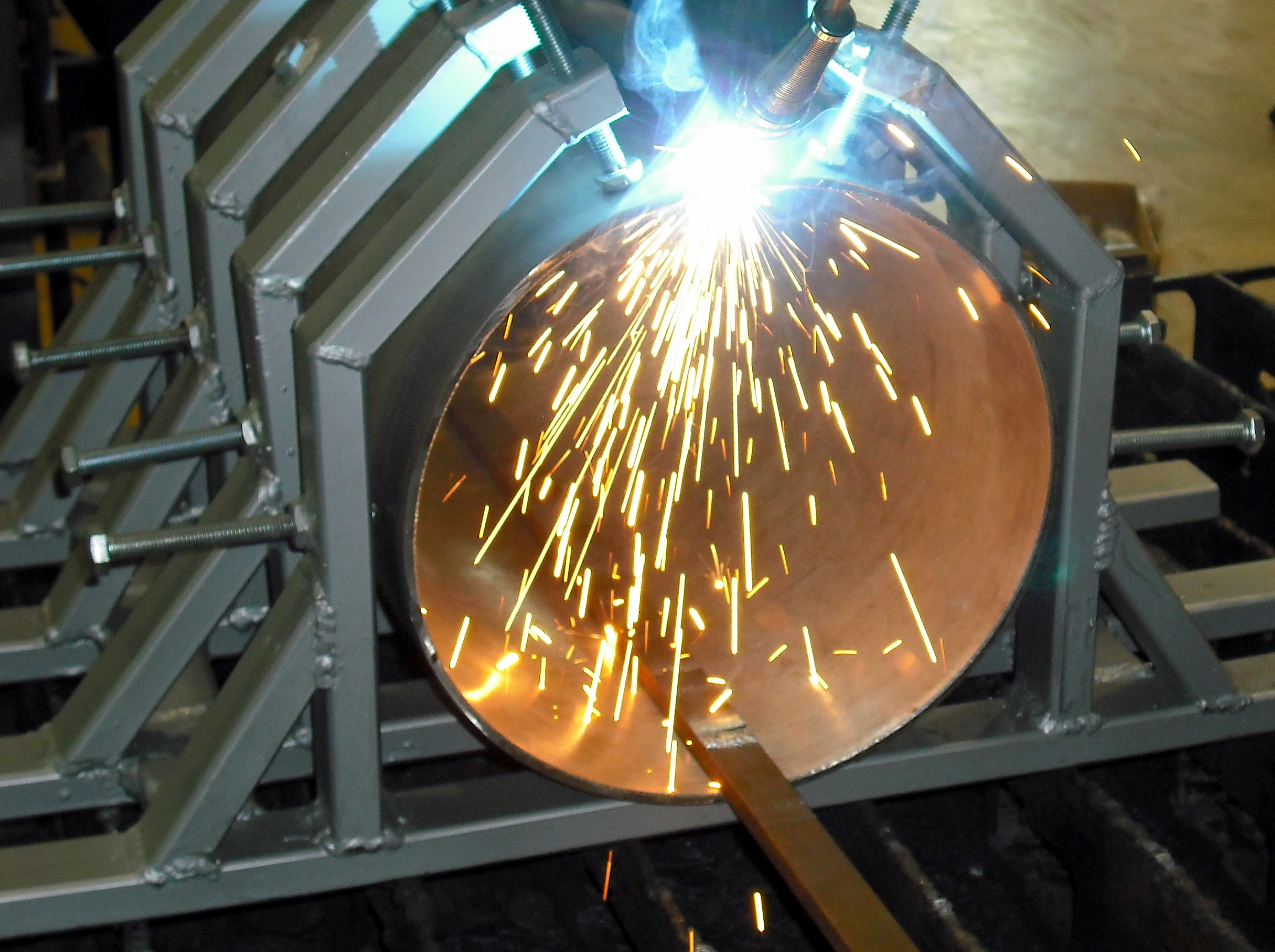
Why can the same current or laser power produce a different pool?
A machine setting does not fully describe how heat reaches the joint. The heat-source footprint, travel speed, absorption, joint contact, and surrounding heat sinks all affect the result. Two trials can share one displayed setting while differing in several of these conditions.
For laser welding, NIST measurements show that absorption changes during the process as the surface and keyhole develop. Therefore, equal incident power does not always mean equal absorbed power. [9]
A simple travel-speed example
For a steady laser beam, incident energy per unit weld length is:
Line energy (J/mm) = laser power (W) ÷ travel speed (mm/s)1,200 W at 20 mm/s60 J/mm
1,200 W at 40 mm/s30 J/mm
This is an illustrative calculation, not a recommended welding recipe. Doubling travel speed halves the incident energy per unit length in this example. It does not prove that penetration halves: absorption, spot size, liquid flow, and heat loss also influence the weld.
Likewise, two beams with equal power but different spot sizes have different intensity distributions. Defocus or wobble can spread the energy over a larger area. In arc welding, arc length and electrode geometry can change the heat and current distributions. Record these conditions before concluding that “the power is too low.”
The practical distinction is explained further in laser welding power versus penetration depth.
What can weld-pool appearance tell you—and what should you check?
Appearance is a useful signal, not a diagnosis. Use a change in the pool to decide what evidence to collect. The checks below are an investigation order, not permission to change a qualified welding procedure.
On a small screen, scroll the table sideways to read all columns.
| What you notice | Possible explanations | Check first | How to confirm |
|---|---|---|---|
| A wider, apparently shallow pool | A broader heat footprint, altered surface flow, faster heat loss, or insufficient energy reaching the joint. | Material heat and surface condition; arc geometry or laser focus/spot; actual travel speed and setup. | Compare representative cross-sections. A top view cannot establish depth. |
| A long tail or repeating humps | The moving heat source, liquid transport, deposition, and freezing are no longer balanced. | Travel consistency, torch angle, transfer mode where applicable, and the point where the shape changes. | Match recorded process behavior to bead profile and section evidence. |
| Sagging or excessive root drop-through | More liquid is present than the joint and solidifying region can support under the current conditions. | Welding position, gap, backing, molten volume, filler delivery, and the approved operating window. | Inspect root profile, dimensions, and fusion against the applicable acceptance criteria. |
| Spatter, sudden ejection, or intermittent pores | Unstable transfer or keyhole behavior, surface contamination, coating vapor, or gas-related disturbance. | Identify whether the process is arc, conduction laser, or keyhole laser; then check the relevant transfer, optics, gas, and material variables. | Combine process observations with defect location and suitable internal inspection. |
| Poor spreading at one edge | Uneven heat placement, torch alignment, surface films, joint mismatch, or a local heat sink. | Compare both joint faces, edge preparation, alignment, fixture contact, and the actual beam or arc position. | Check that edge in a section or another appropriate fusion assessment. |
If the problem began after a new material heat, fixture, consumable, gas setup, or optical adjustment, record that change before altering several parameters. Changing everything at once makes the cause harder to identify.
How do you confirm penetration and weld quality?
Inspect the solidified joint using methods suited to the requirement. Visual inspection can identify surface profile, undercut, and some open defects. It cannot rule out internal lack of fusion or porosity.
A prepared and etched cross-section can show the fusion boundary, penetration, root shape, and defects intercepted by that slice. It is sampled evidence: one good section does not prove that every location along the weld is sound.
Depending on the part and acceptance specification, the inspection plan may also require mechanical, leak, or nondestructive testing. Those tests answer different questions; a leak-tight joint is not automatically proof of full penetration. See how weld penetration is defined and checked.
Watch what happens as the pool freezes
Solidification cracking can occur when the last liquid cannot feed the shrinking, strained region adequately. Alloy chemistry, restraint, and weld shape all matter. A long, narrow pool tail or an unfilled end crater may increase concern, but neither appearance alone establishes the cause.
TWI’s guidance connects crack risk with composition, feeding, geometry, and contraction. Investigation should therefore include the material and joint restraint—not only the heat setting. [10]

How should you investigate an unexpected change in the weld pool?
Use a controlled comparison. The objective is to connect a documented change with a repeatable result, while remaining inside the authorized procedure and safety controls.
- Record the starting condition
Identify the material heat, thickness, joint, gap, position, fixture, filler, shielding, and equipment setup. Keep a known-good sample or reference record where available.
- Verify the actual process
Check that the torch or head, travel, gas delivery, and consumables match the welding procedure specification (WPS). For laser work, include the relevant focus and optical configuration.
- Make an authorized comparison
Change one suspected variable at a time when the procedure permits. If the proposed change falls outside the qualified range, refer it for the required engineering and qualification review.
- Check and document the result
Compare pool observations with the agreed inspection results. Repeat enough to establish consistency for the intended use. Keep the result with the setup details, not as an isolated photograph.
Two practical questions about observing the weld pool
Can the color of a weld pool tell you its exact temperature?
Not from an ordinary visual observation or photograph. Surface condition, emitted light, the arc, camera exposure, and the viewing filter affect apparent color. A temperature measurement needs a suitable, calibrated method and a clear account of what it measures.
Do not remove or weaken protective filters to obtain a clearer view. Use protection selected for the actual process; arc-welding lens guidance is not a substitute for laser-specific protection. OSHA’s protective-equipment guidance explains the need to match protection to the hazard.
Should pool observations be included in a work instruction?
Yes, when they give the operator a repeatable check or stop condition. Use specific observations such as consistent wetting at both edges, a defined monitoring range, or a clearly illustrated abnormal condition. “The pool should look good” is too vague.
Keep observation criteria separate from final weld acceptance. A process signal can tell the operator when to stop or request a check without replacing the required inspection or authorizing a change to the WPS.
Need to evaluate laser welding on your actual joint?
Share the material grade, thickness, joint drawing or photos, gap range, and required penetration with Oceanplayer Laser. Include the defect or pool behavior you want to investigate and the inspection method your application requires.
Discuss your welding applicationTechnical references
- Mills & Keene, Factors affecting variable weld penetration (1990). Surface-tension behavior and chemistry-dependent penetration.
- Mills & Guo, The Importance of Materials Properties in High-temperature Processes (2014). Variable TIG penetration and the surface-flow mechanism, Figures 1–4.
- Wang, Shi & Tsai, Modeling of the Effects of Surface-Active Elements on Flow Patterns and Weld Penetration (2001). A stationary 304 stainless-steel GTAW model; not a universal process rule.
- The Effects of Process Parameters on Melt-pool Oscillatory Behaviour in Gas Tungsten Arc Welding (2021). Position, operating conditions, and changing pool dynamics.
- High-speed GTAW driving-force study, International Journal of Heat and Mass Transfer (2017). Arc pressure, surface shear, and defect formation.
- Cho & Na, Impact of driving forces on molten pool in gas metal arc welding (2021). Droplet impact and interacting flow mechanisms.
- NIST, A Little Light Construction: Laser Welding in Three Acts. Evaporation, cavity formation, and laser–material interaction.
- Characterization of Vapor Capillary Geometry in Laser Beam Welding of Copper with 515 nm and 1030 nm Laser Beam Sources (2023). Keyhole pressure balance and in-situ X-ray observations.
- NIST, Measuring Dynamic Light Absorption during Laser Welding and Laser Powder Bed Fusion. Why energy coupling changes during a weld.
- TWI, Defects: solidification cracking. Feeding, composition, restraint, and crack investigation.
Oceanplayer Laser · Welding and manufacturing knowledge