
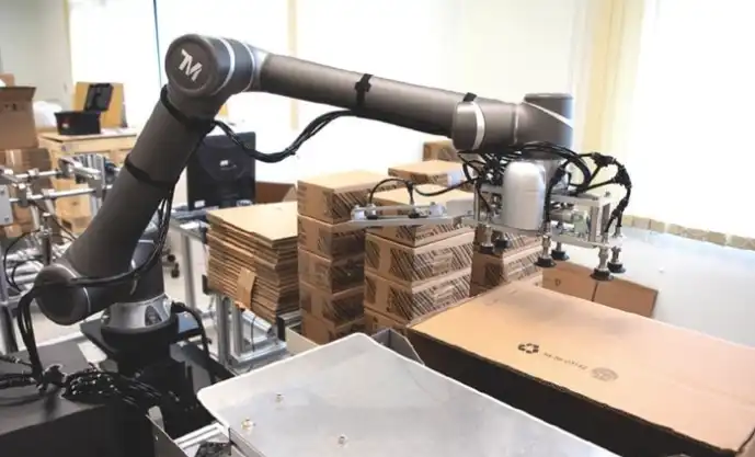
Over 60% of cobot deployment failures trace back to one root cause: the integrator miscalculated the actual payload requirement. That’s not a guess — it’s a pattern documented across hundreds of support cases by major manufacturers like Universal Robots. Getting cobot payload capacity explained correctly means understanding that the number on a spec sheet is never the number you can actually use. Payload capacity is the maximum weight a collaborative robot can safely handle at its wrist flange — but your gripper, sensor, bracket, and the workpiece’s center of gravity all eat into that limit before a single production part is picked up.
What Exactly Is Cobot Payload Capacity
Cobot payload capacity is the maximum mass a collaborative robot can support at its tool flange — and that number must cover everything attached beyond that flange. Gripper, sensor, bracket, cable dress-out, the workpiece itself: all of it counts. If a cobot is rated at 5 kg and your gripper weighs 2.1 kg, you have exactly 2.9 kg left for the part you’re moving. Exceed that limit and you risk servo faults, premature joint wear, or — worst case — a safety-rated stop that halts your production line.
This is where many newcomers confuse cobot specs with traditional industrial robot ratings. An industrial robot rated at 210 kg payload operates behind safety fencing at high speeds; its payload figure assumes rigid mounting, fixed trajectories, and no human proximity. A cobot’s payload rating, by contrast, is validated under ISO/TS 15066 safety constraints — meaning force and power limiting are baked into the number. Push a cobot past its stated capacity and you don’t just lose performance; you compromise the safety case that lets it work alongside people without guarding.
Here’s a detail most spec sheets bury: the published payload is only valid at a specific center-of-gravity offset from the flange. Universal Robots, for example, rates the UR10e at 12.5 kg — but only when the center of gravity sits within 50 mm of the flange face. Move that CG further out and the effective payload drops sharply. We’ll cover those payload-moment curves in a later section.
Practical rule of thumb: Budget no more than 70–80% of the rated payload for your combined tooling and part weight. That margin absorbs inertial forces during acceleration and gives you headroom for fixture changes down the road.
Getting cobot payload capacity explained upfront — before you spec grippers or design fixtures — saves costly mid-project redesigns. Treat the flange rating as your hard ceiling, subtract every gram of tooling, and only then decide if the remaining capacity fits your heaviest workpiece. That single calculation is the starting point for every successful cobot deployment.
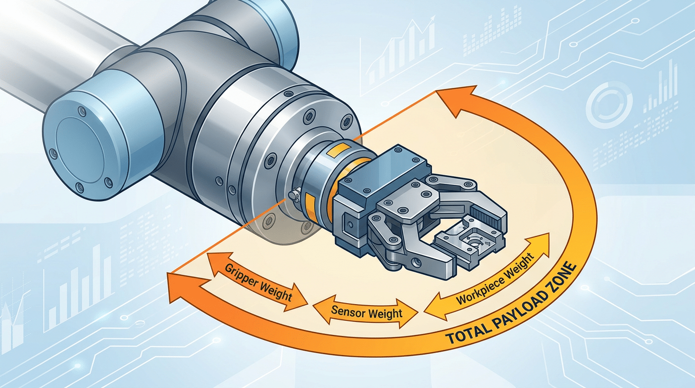
Cobot payload capacity explained with labeled diagram showing tool flange, gripper, and workpiece weight distribution
Why End-of-Arm Tooling (EOAT) Always Reduces Your Usable Payload
Here’s the number that catches most first-time integrators off guard: EOAT typically consumes 30–70% of a cobot’s rated payload before a single workpiece touches the gripper. When cobot payload capacity is explained in datasheets, that headline figure includes everything bolted to the tool flange — gripper, sensor stack, camera, tool changer, cables, and adapter plates. Your actual part-handling budget is whatever’s left over.
Typical EOAT Weights You Should Plan For
| EOAT Category | Example | Approximate Weight |
|---|---|---|
| Pneumatic parallel gripper | Schunk Co-act EGP-C 40 | 0.35 kg |
| Electric adaptive gripper | Robotiq 2F-85 | 0.90 kg |
| Force/torque sensor | ATI Axia80 | 0.29 kg |
| Vision camera | Cognex In-Sight 2800 | 0.15 kg |
| Automatic tool changer | ATI QC-7 | 0.54 kg (both halves) |
| Mounting bracket/adapter plate | Custom aluminum plate | 0.10–0.30 kg |
Stack a tool changer, a force/torque sensor, and an electric gripper on a 5 kg cobot and you’ve already burned through roughly 1.7 kg — leaving just 3.3 kg for the part itself. That’s a 34% reduction from the spec sheet number.
Pro tip: always weigh your complete EOAT assembly on a calibrated scale rather than summing catalog values. Cable harnesses, pneumatic fittings, and 3D-printed finger inserts routinely add 100–200 g that datasheets never mention.
The Universal Robots payload guidelines explicitly state that rated capacity includes tool weight — a detail some buyers overlook until commissioning day. Getting cobot payload capacity explained upfront, with EOAT subtracted, prevents costly mid-project cobot upsizing.
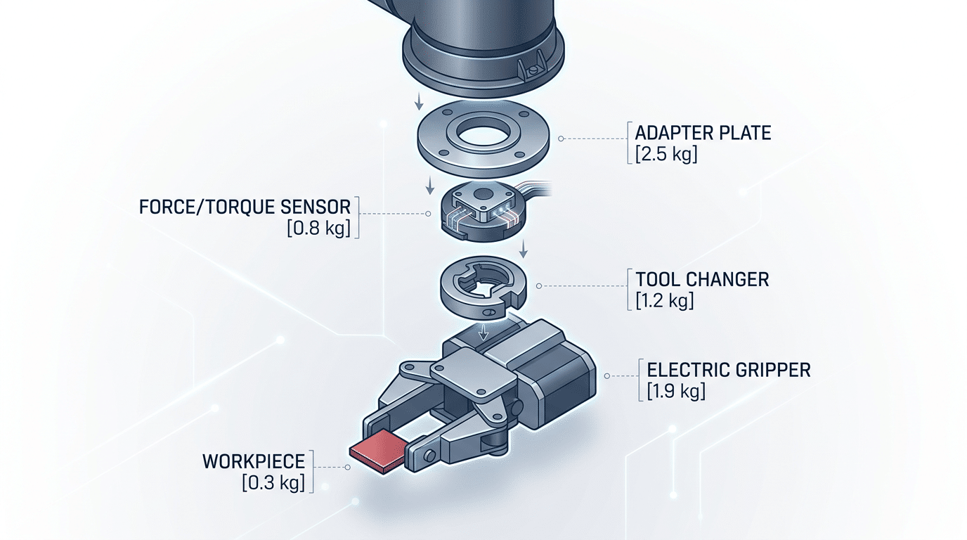
EOAT weight breakdown reducing usable cobot payload capacity
How Center of Gravity and Offset Distance Affect Real Capacity
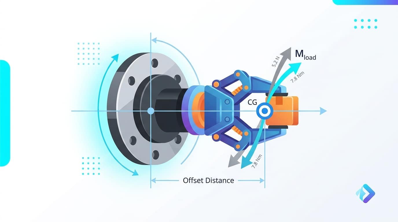
The payload number on a datasheet assumes the load’s center of gravity (CoG) sits directly at the tool flange center — essentially zero offset. Move that CoG even 50 mm outward, and the effective capacity drops fast. This is the single most misunderstood aspect of cobot payload capacity explained in manufacturer documentation.
Why? It comes down to moment load — the torque exerted on the wrist joint, calculated as mass × offset distance. A 3 kg part held 100 mm from the flange generates a 2.94 N·m moment. Mount that same part on a 150 mm extended-finger gripper, and the total offset might reach 250 mm, pushing the moment to 7.35 N·m. Many cobots cap their wrist moment at around 10–12 N·m, so you can see how quickly you approach the limit without ever exceeding the raw kilogram rating.
Rule of thumb from experienced integrators: every additional 50 mm of offset can reduce your usable payload by roughly 15–25%, depending on the cobot’s joint torque budget.
Offset brackets, tool changers, and long pneumatic grippers are the usual culprits. A typical ATI tool changer adds about 30–40 mm of offset before your gripper even begins. Stack that with gripper finger length, and the CoG lands far from the reference point the manufacturer used during testing. Universal Robots, for example, publishes detailed payload vs. CoG offset curves for each model — ignoring these curves is one of the fastest ways to trigger protective stops or accelerate joint wear.
Inertia limits matter too. Rotational inertia (measured in kg·m²) increases with the square of the offset distance, meaning small changes in geometry create disproportionately large inertia spikes during fast wrist rotations. Always check both the moment load and the inertia spec — satisfying one doesn’t guarantee you satisfy the other.
Skip guesswork. Model your full tool assembly in the manufacturer’s payload calculator, input the combined CoG offset, and verify that moment and inertia stay within limits before committing to hardware.
Cobot payload center of gravity offset distance and moment load diagram explaining real capacity reduction
Step-by-Step Guide to Calculating Your Total Payload Requirements
Getting cobot payload capacity explained in theory is one thing — running the actual numbers for your application is where projects succeed or fail. Here’s the practical method experienced integrators use before selecting a cobot.
The Core Formula
Start with this straightforward equation:
Total Payload = EOAT Weight + Adapter/Coupling Plate Weight + Maximum Workpiece Weight
Every component bolted to the tool flange counts. That includes force-torque sensors, tool changers, camera brackets — everything. Miss a single 0.3 kg adapter plate and you risk exceeding the rated limit under peak conditions.
Worked Example with Realistic Numbers
Suppose you’re deploying a UR10e (12.5 kg rated payload) for a machine-tending task:
| Component | Weight |
|---|---|
| Pneumatic gripper (e.g., Schunk Co-act EGP-C 40) | 0.95 kg |
| Adapter plate + pneumatic fittings | 0.35 kg |
| Heaviest workpiece (aluminum housing) | 9.80 kg |
| Total | 11.10 kg |
That leaves only 1.4 kg of headroom — roughly 11% of rated capacity. Most integrators target at least a 15–20% safety margin to account for production variability and future part changes.
Verify Against Moment and Inertia Limits
Raw weight alone doesn’t clear you. You must check the moment load (torque at the wrist joint) and inertia values against the manufacturer’s specifications. Universal Robots, for example, publishes a free payload calculation tool in their user manual that cross-references CoG offset with allowable payload. Plug in your total weight and the measured distance from the tool flange to the combined center of gravity. If either moment or inertia exceeds the limit, you need a lighter EOAT or a higher-payload cobot — no exceptions.
Pro tip: Weigh your fully assembled end-effector on a scale rather than trusting catalog specs. Real-world assemblies with cables, hoses, and brackets routinely come in 10–15% heavier than the sum of listed component weights.
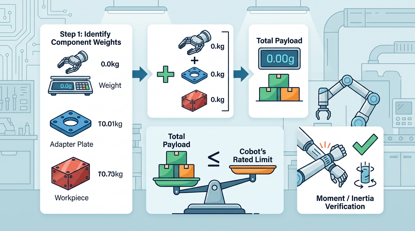
Step-by-step cobot payload capacity calculation formula with worked example showing EOAT, adapter, and workpiece weights
Reading and Interpreting Manufacturer Payload Curves
You’ve calculated your total payload and offset — now you need to verify it against the manufacturer’s actual data. Every major cobot brand (Universal Robots, FANUC, ABB, Doosan) publishes a payload-versus-offset chart, sometimes called a payload moment curve. This is where cobot payload capacity explained on a datasheet meets real-world validation.
The X-axis represents the distance (in millimeters) from the tool flange face to the load’s center of gravity — your offset distance. The Y-axis shows the maximum allowable mass (in kilograms) at that offset. The curve slopes downward: as offset increases, permissible payload drops. On a UR10e, for example, the rated 12.5 kg payload applies only when the CoG sits within 0–50 mm of the flange. Push that offset to 150 mm and the allowable mass can fall below 8 kg.
Pro tip: Plot your configuration as a single point on the chart — X = your calculated offset, Y = your total load mass. If that point lands below the curve, you’re within the safe operating zone. If it lands on or above the curve, you must reduce mass, shorten offset, or select a higher-payload model.
Falling outside the safe zone doesn’t just void your warranty. The cobot’s internal torque sensors will trigger protective stops mid-cycle, killing throughput. Some integrators try to bypass these limits in the software — never do this. Joint overloading accelerates harmonic drive wear and can cause a failure within months rather than the typical 35,000-hour service life.
Always download the official payload chart from the manufacturer’s support portal rather than relying on reseller summaries. Universal Robots’ payload documentation is a solid reference for understanding how these curves are structured across different models.
How Payload Capacity Interacts with Speed and Reach
A cobot rated at 12 kg doesn’t always deliver 12 kg of usable capacity. Speed and reach create a dynamic triangle: push one variable higher, and the others must come down. Most buyers evaluate payload in isolation — a costly oversight once the cell is built and the robot can’t hit cycle time.
The Speed-Payload Trade-Off
Running at maximum payload typically forces you to reduce TCP (tool center point) speed by 30–50% compared to the robot’s top rated speed. Why? Higher mass increases joint torques and stopping distances. If the cobot can’t stop within its safety-rated deceleration window, the controller automatically throttles velocity. In practice, a UR10e carrying 12.5 kg near full extension may only sustain around 1 m/s TCP speed — well below its 1.5–2 m/s maximum.
Reach Compounds the Problem
Longer moment arms amplify torque on the base and shoulder joints. Operating at 90–100% of maximum reach while carrying a heavy payload pushes those joints toward their torque limits, triggering further speed reductions or outright motion faults. The sweet spot? Keep your working envelope within roughly 70–80% of maximum reach when payload exceeds 75% of the rated limit.
ISO/TS 15066 Adds Another Constraint
Collaborative safety standards cap permissible force and pressure during human contact. ISO/TS 15066 defines quasi-static and transient contact limits — for example, 150 N maximum on the chest during transient impact. A heavier payload increases effective mass in a collision, so the cobot must slow down even further to stay within these biomechanical thresholds. The result: your “usable” payload during true collaborative operation — where a human is nearby — can be significantly lower than the datasheet number.
Pro tip: When getting cobot payload capacity explained by a vendor, always ask for cycle-time estimates at your actual working speed and reach, not just the static payload rating. The gap between marketing specs and real-world throughput lives in this triangle.
Common Payload Sizing Mistakes and How to Avoid Them
Even experienced integrators get tripped up by payload sizing — and the consequences range from nuisance faults to catastrophic joint failures. A Universal Robots technical guide emphasizes that roughly 40% of support tickets related to performance issues trace back to incorrect payload or center-of-gravity configuration. That’s not a fringe problem; it’s the single most common setup error.
The Mistakes That Keep Showing Up
- Forgetting EOAT weight entirely. A 2.1 kg gripper on a 5 kg cobot leaves you just 2.9 kg for the actual workpiece. Obvious? Yes. Still missed constantly during initial quoting.
- Ignoring moment and inertia loads. Payload specs assume a compact mass near the flange. Mount a long finger gripper with a 150 mm offset and your effective capacity drops — sometimes by 30% or more — even if the mass is technically under the limit.
- Sizing to exactly 100% of rated capacity. Zero margin means zero room for product variation, fixture wear, or a future tool swap. One extra cable gland pushes you over.
- Assuming payload stays constant across the workspace. As covered in earlier sections, extending the arm to full reach or running at high TCP speeds reduces usable capacity. Sizing at the nominal spec without checking the payload-reach curve is a recipe for random protective stops.
Rules of Thumb That Actually Work
Maintain a 20–30% payload safety margin above your calculated total load. If your EOAT plus heaviest workpiece totals 7.5 kg, target a cobot rated for at least 10 kg. This buffer absorbs tooling upgrades, part weight tolerances, and the inevitable “can we add a sensor to the gripper?” request six months post-deployment.
When cobot payload capacity is explained without addressing these pitfalls, teams end up re-specifying hardware mid-project — adding weeks and thousands of dollars to the timeline.
Document every gram. Create a payload budget spreadsheet listing gripper body, fingers, adapter plate, sensors, cables, and fasteners individually. Weigh components on a calibrated scale rather than trusting catalog values, which can be off by 5–10%.
Comparing Payload Ranges Across Popular Cobot Models
With cobot payload capacity explained through calculations and curves, the next step is matching your numbers to an actual robot. The market splits neatly into three payload tiers, each targeting distinct application profiles.
| Payload Tier | Typical Range | Representative Models | Best-Fit Applications |
|---|---|---|---|
| Light | 3–5 kg | Universal Robots UR3e, FANUC CRX-5iA | PCB assembly, lab automation, small-part inspection |
| Medium | 10–12 kg | UR10e, Doosan M1013, ABB GoFa 10 | Machine tending, pick-and-place, packaging |
| Heavy | 16–25 kg | UR20, FANUC CRX-25iA, KUKA LBR iisy 15 | Palletizing, heavy part handling, material removal |
The 10–12 kg class dominates roughly 60% of new cobot deployments worldwide, according to Universal Robots’ product data. That popularity makes sense — a 10 kg rating leaves about 7–8 kg of usable capacity after typical EOAT, which covers the vast majority of factory parts under 5 kg.
Don’t default to the heavy tier “just in case.” A 25 kg cobot costs 40–70% more than a 10 kg model, occupies a larger footprint, and often requires a reinforced mounting surface. Over-specifying wastes capital and floor space.
Pro tip: If your calculated total payload lands within 85% of a tier’s maximum, step up one class. Operating near the limit forces slower cycle times and accelerates joint wear — problems that erode ROI faster than the upfront price difference.
For applications straddling two tiers, request loaner units from distributors. A real-world cycle test at production speed reveals whether the lighter model truly sustains throughput, something no datasheet can guarantee.
Frequently Asked Questions About Cobot Payload Capacity
Does mounting orientation change payload capacity?
Yes — but less than you might expect. Most cobot manufacturers rate payload identically for floor, wall, and ceiling mounts because the joints compensate for gravitational direction. The real impact is on joint torque distribution. A ceiling-mounted cobot lifting a 10 kg load at full extension puts different stress on joints 1 and 2 compared to a floor mount. Universal Robots, for example, lists the same 5 kg rating for the UR5e regardless of orientation, but their mounting guidelines specify that cable routing and joint limits may differ, which indirectly affects usable workspace and effective payload at certain poses.
How should I handle variable-weight parts?
Always size for the heaviest part in your production mix. If your parts range from 0.8 kg to 3.2 kg, your payload budget must accommodate 3.2 kg plus full EOAT weight. Running lighter parts won’t hurt the cobot — running heavier ones will trigger force limits or protective stops. For mixed-weight applications, configure separate motion profiles: slower speeds and reduced reach for the heaviest items, faster cycles for lighter ones.
Does exceeding rated payload void the warranty?
Almost universally, yes. Overloading by even 5–10% can void coverage because manufacturers log joint torque data internally. During a warranty claim, that telemetry gets reviewed. Fanuc and ABB both include explicit overload exclusions in their standard terms.
What’s the difference between static and dynamic payload?
Static payload is the mass the cobot can hold while stationary. Dynamic payload — the figure that actually matters — is what it can carry while moving at operational speed. Dynamic ratings are typically 15–20% lower than static ratings because acceleration forces add effective weight. When you see cobot payload capacity explained on a datasheet, the headline number is almost always the dynamic rating at nominal speed.
Actionable Summary and Next Steps for Choosing the Right Payload
With cobot payload capacity explained across every critical dimension — from EOAT deductions to moment-inertia limits to speed-reach trade-offs — here’s what actually matters when you make a purchasing decision.
Five Non-Negotiable Takeaways
- Calculate total system weight first. Add gripper, adapter plate, sensor, cabling, and workpiece. The part you’re moving is often less than half the total load on the flange.
- Verify against moment and inertia limits, not just the kilogram rating. A payload that passes the mass check can still fail if the center of gravity sits 120 mm or more from the flange face.
- Maintain a 20–25% safety margin. Production conditions drift — grippers wear, parts vary in weight, and operators swap fixtures. That buffer keeps you inside the payload curve long-term.
- Match payload class to your application roadmap. If you plan to add vision or force-torque sensing within 18 months, account for that EOAT weight now rather than discovering you’ve maxed out the flange.
- Cross-check with the manufacturer’s payload calculator. Datasheet numbers are starting points. The actual allowable load depends on your specific reach, orientation, and cycle speed.
Your Concrete Next Step
Open your target manufacturer’s online tool — Universal Robots offers a free payload file and calculator for every e-Series model. Input your exact EOAT mass, CoG offset, and desired TCP speed. If the tool flags a red zone, you need either a higher-payload model or a lighter end-effector — not a slower cycle time workaround.
Still uncertain? Engage a certified integrator for a physical validation test. A 2-hour bench check costs far less than discovering a payload mismatch after deployment, where unplanned downtime in manufacturing averages $260,000 per hour according to Forbes reporting on industry data. Get the numbers right before the cobot hits the floor.
See also
Ultimate Guide — 14k/18k Gold Melting Point Chart
What Is a Collaborative Robot and How Does It Work
How to Integrate a Cobot Into Your Production Line
How to combine laser cleaning machine with industrial robots


