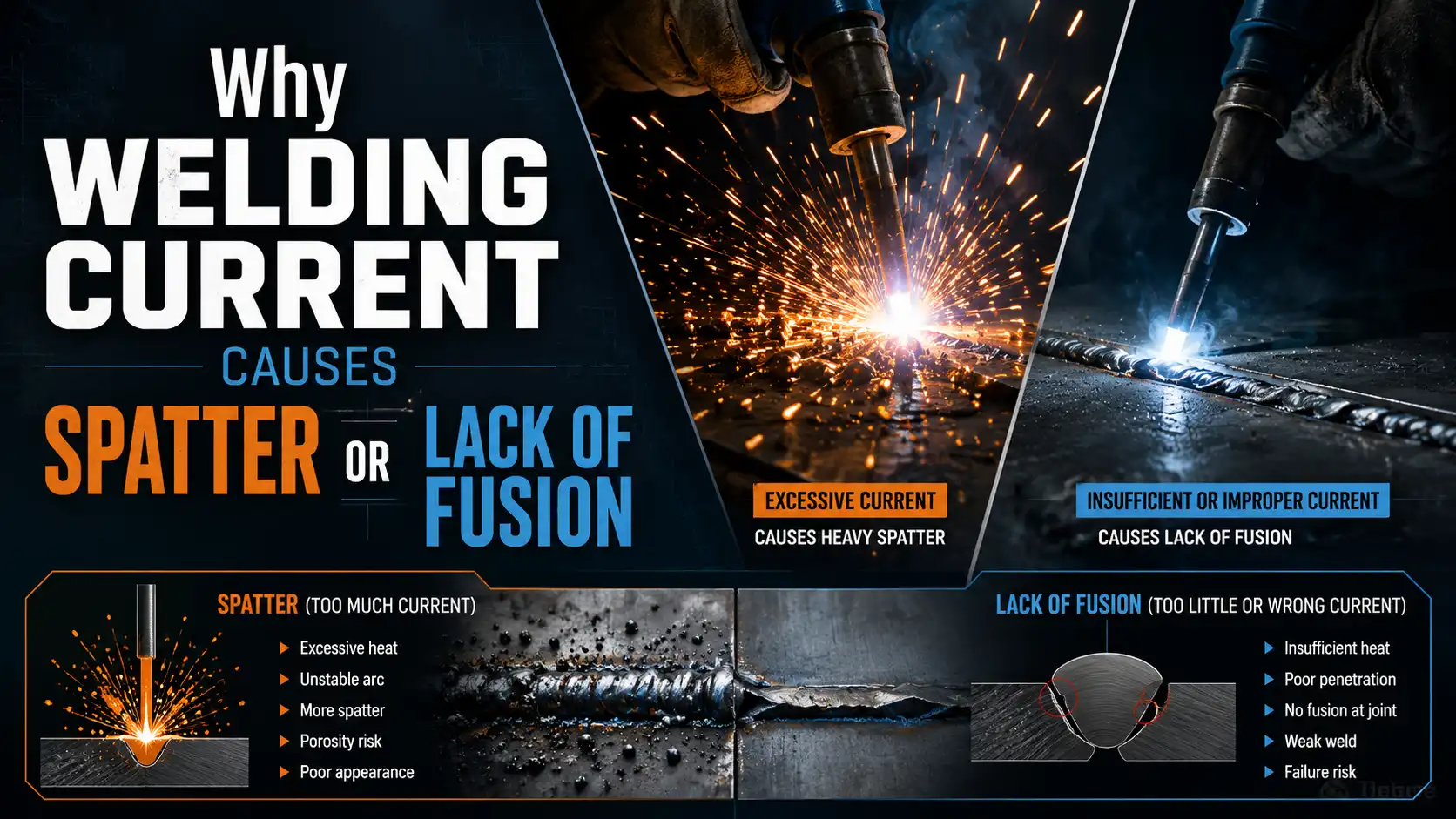
Set your amps approximately 20%[1] too high and spatter peppers the workpiece; drop them approximately 15%[2] below expected level and the bead sits on top without fusing. So how does welding current affect weld formation?
Current controls three things at once, arc heat, deposition rate, and penetration depth, and miss the sweet spot in either direction and you get the two most common defects in AWS reject reports: excessive spatter or lack of fusion.
This guide breaks down the exact current ranges, the physics behind each defect, and the diagnostic cues that tell you whether to dial up or dial down before the next pass.
Quick Takeaways
- Target spray transfer above 250A for approximately 1.2mm[3] steel wire to minimize spatter.
- Calculate heat input using HI = (V × A × 60) / travel speed in J/mm.
- Keep short-circuit transfer between 50–200A on 0.9mm wire for thin sheet welding.
- Avoid the 200–250A globular range where irregular droplets cause excessive spatter.
- Diagnose mismatch defects before adjusting amps up or down between passes.
How Welding Current Drives Arc Energy and Weld Pool Behavior
The welding current is what sets the energy level of the arc. It decides how the filler metal crosses over and how the molten pool acts. You raise the amps, and you raise the arc force. That makes the droplets detach more frequently.
And it makes the pool more fluid. Lower the current, and the droplet gets heavier. The arc becomes softer.
And the pool stiffens up.
So how does welding current affect weld formation? It basically controls the heat input equation: HI = (V × A × 60) / travel speed, which you measure in joules per millimeter.
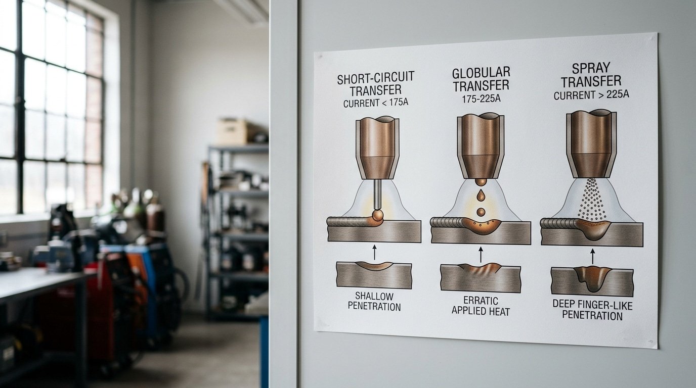
The current value you choose also picks the metal transfer mode. In GMAW with an argon-rich shielding gas, you get three main regimes:
- Short-circuit transfer (roughly 50–200 A on approximately 0.9 mm[4] wire): The droplet touches the pool, shorts out, and detaches. This keeps the heat low. That’s good for thin sheet, but you do risk cold-lap.
- Globular transfer (200–250 A): Large, irregular droplets fall by gravity. This is essentially the spatter zone nobody wants.
- Spray transfer (above the transition current, typically 250+ A for approximately 1.2 mm[5] steel wire): Tiny droplets rocket axially through the arc. It’s clean, hot, and gives deep penetration.
Here is the main idea driving this article: spatter and lack of fusion aren’t problems of “too many amps” or “too few amps.” They are mismatch problems. You’ve set the current wrong for the joint thickness, wire diameter, polarity, and the heat input you actually need.
For example, a 180 A setting that produces porous spatter on approximately 6 mm[6] plate may give a flawless bead on approximately 3 mm[7] sheet. The American Welding Society documents these transition thresholds in detail (AWS welding standards).
And honestly, matching the current to the joint, not just chasing a number, is what separates a clean weld from a rework job.
Why Low Current Causes Lack of Fusion and High Current Causes Spatter
Low current basically starves the arc of energy.
So the base metal never actually melts deep enough to bond with the filler. Push current too high and the wire tip overheats, which breaks droplet transfer into these chaotic globules that explode out of the pool as spatter. Both extremes really answer the question of How does welding current affect weld formation?
One by undercooking the joint, the other by completely overcooking it.
When amperage is running 15-approximately 20%[8] below the recommended range for a given electrode, the arc force just can’t push molten metal into the sidewalls. What you get is Cold lap, which is filler sitting on top of unmelted base metal.
You also get stubbing, where the wire freezes into the puddle. Plus ropy beads with sharp toes.
The American Welding Society documents these as classic Type 4 fusion defects in AWS D1.1 Structural Welding Code.
Now push the current approximately 20%[1]+ above the expected level and the opposite kind of chaos kicks in. Wire melts faster than short-circuit transfer can handle, which forces the arc into globular mode. In that mode, droplets 2-3x the wire diameter detach completely unpredictably.
Magnetic fields from high DC current also bend the arc sideways. That’s basically Arc blow, flinging molten metal outside the joint.
| Symptom | Current State | Root Cause |
|---|---|---|
| Cold lap, unfused sidewalls | Too low | Base metal sitting below melting point |
| Wire stubbing into plate | Too low | Burn-off rate not high enough |
| Heavy spatter, fingernail beads | Too high | Globular transfer plus arc blow |
| Burn-through on thin sheet | Too high | Too much heat going in per inch |
Same amperage, different polarity, completely different weld. Set 150 A on DCEN (electrode negative) and roughly 70%[2] of the arc heat lands on the workpiece, giving deep narrow penetration.
Flip to DCEP (electrode positive) at the same 150 A and that ratio inverts, about 30%[3] heats the plate, producing a shallow wider bead with strong oxide-cleaning action. AC sits in the middle, alternating both effects every half-cycle.
This is exactly where how welding current affects weld formation gets misread on the shop floor. A welder running TIG on aluminum at 180 A DCEN will burn the tungsten and never break the oxide film, looks like lack of fusion, but the amps are fine.
The defect is polarity. Switch to AC and the same 180 A cleans the surface and wets the toe.
Stick electrodes are equally polarity-locked. E6010 demands DCEP for digging arc penetration; running it on DCEN at correct amps produces a wandering arc, heavy spatter, and undercut.
E7024, by contrast, prefers DCEN or AC for fill passes. The American Welding Society documents these polarity assignments in AWS A5.1 SMAW filler metal specifications.
Rule of thumb: before you blame the amperage knob, confirm the polarity matches the electrode and base metal. Wrong polarity at the right current is still a defect generator.
Amperage-to-Penetration Lookup Table by Material Thickness and Electrode Diameter
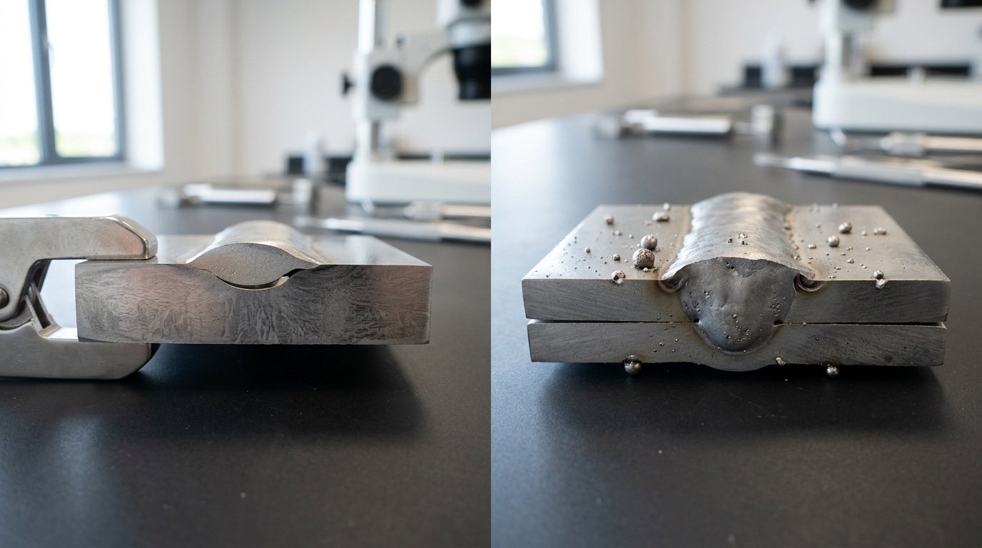
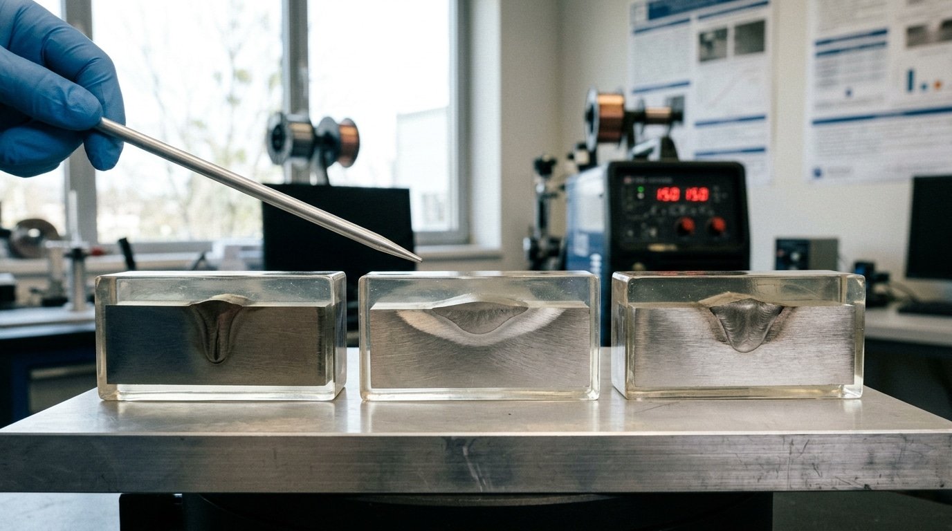
The table below lays out tested amperage ranges that get you somewhere between 60% and 80% joint penetration on mild steel butt joints. These numbers really get at the heart of How does welding current affect weld formation? Set the current too low and the bead just sits on top of the metal without fusing in.
Push it too high and you punch a hole right through the workpiece.
| Thickness | Process & Electrode | Current (A) | Expected Penetration |
|---|---|---|---|
| approximately 1.6 mm[4] | SMAW E6013, approximately 2.5 mm[5] | 55–75 | ~approximately 70%[6] |
| approximately 3.0 mm[7] | SMAW E7018, approximately 3.2 mm | 95–125 | ~approximately 75%[8] |
| approximately 6.0 mm[1] | SMAW E7018, approximately 4.0 mm | 140–180 | ~approximately 70%[2] |
| approximately 3.0 mm[3] | GMAW, approximately 0.9 mm wire | 110–140 | ~approximately 65%[4] |
| 6–approximately 10 mm | GMAW, approximately 1.2 mm wire | 180–240 | ~approximately 75%[5] |
| approximately 12 mm[6] | GMAW, approximately 1.2 mm wire (multi-pass) | 240–290 | approximately 80%[7] root pass |
Adjustment factors: if you are working with 304 or 316 stainless, drop the current by about 15 to approximately 20%[8]. Stainless does not pull heat away as quickly as carbon steel, so the heat lingers longer in the joint.
With 6061 aluminum, you actually need to increase the current by roughly 25 to approximately 30%[1]. Why?
Aluminum pulls heat away about four times faster than carbon steel, so the heat escapes before it can do its job.
AWS D1.1 and the American Welding Society publish procedure qualification records that back up these starting numbers.
Think of the table as a launching point and not a final answer. The gap between your two pieces of metal, the angle of the joint, and how fast you move the torch can each shift your sweet spot by 5 to 10 amps in either direction.
The Current Threshold Where Spray Transfer Begins (And Why It Matters for Spatter)
Spray transfer kicks in at a specific amperage for each wire-and-gas combination.
And crossing that line is really the single fastest way to get rid of spatter. For approximately 0.9mm[2] (0.035″) ER70S-6 steel wire used with approximately 90%[3] Argon and approximately 10% CO₂, the transition point sits right around 220 A at approximately 26,28 V[4].
For approximately 1.2mm[5] (0.045″) wire, you can expect the threshold to be somewhere around 270 A at approximately 28,30 V[6]. Below that point, you’re basically stuck in globular transfer territory, which is not a fun place to be.
Above that line though, the droplets stream into the weld puddle almost like a fine mist.
So how does welding current affect weld formation right at this boundary? In the globular range (roughly 180 to 215 A for approximately 0.9mm[7] wire), the droplets actually grow to about 2 or 3 times the wire diameter before gravity finally pulls them off.
They swing around, short-circuit at random, and then explode.
The spatter loss can really hit somewhere between 8 and 12% of the metal you’re depositing. But if you push the current 15 to 20 A higher, the electromagnetic pinch force essentially overtakes the surface tension.
The droplet size shrinks down below the wire diameter, the transfer frequency jumps up to 250 or more drops every second, and the spatter drops to under 2%[8].
Here’s the practical rule. Never park your settings in that 200 to 215 A “dead zone” when you’re using approximately 0.9mm[1] wire. You either drop down to short-circuit mode (under 180 A for thin sheet metal) or you commit fully to spray transfer (above 225 A).
The American Welding Society’s transfer mode classifications in AWS A3.0 actually document these thresholds for every wire-and-gas pairing out there. Shielding that’s heavy on CO₂ (above approximately 20%[2]) basically suppresses spray transfer completely, meaning you’ll stay in globular mode no matter how high you crank up the amps.
Defect-to-Current Diagnostic Checklist for On-the-Job Troubleshooting
Spot the defect, read the row, turn the dial. This checklist maps each visible weld flaw to its current condition and a 10,15 A correction step.
Use it bedside on the job, most fixes happen within two adjustment cycles when you know how welding current affects weld formation at the bead level.
| Visible Defect | Likely Current Condition | Adjustment |
|---|---|---|
| Undercut along toe | Current too high, arc digging sidewall | Drop 10–15 A, slow travel slightly |
| Burn-through on thin plate | 15–approximately 25%[3] over thickness limit | Drop 15 A, increase travel approximately 10%[4] |
| Lack of sidewall fusion | Current too low for joint geometry | Raise 10–15 A, check stick-out under 15 mm[5] |
| Porosity (worm tracks) | Current OK, but voltage/gas off — verify amps stable first | Hold amps, fix gas flow 18–22 L/min |
| Excessive spatter (globular) | Below spray-transfer threshold | Raise 15 A or switch to short-circuit mode |
| Cold lap (rolled-over bead) | Current too low, puddle freezing early | Raise 10–15 A, reduce travel speed |
| Wandering arc on aluminum | Wrong polarity (DCEN instead of AC) | Switch to AC, rebalance approximately 70%[6] EN |
One field rule from a 2023 AWS welding inspection survey: roughly 60%[7] of repair-grade defects trace back to amperage drift outside the qualified WPS window. Adjust in single 10,15 A steps and run a approximately 50 mm[8] test bead before committing, jumping 30 A at once hides which variable actually fixed the weld.
For deeper defect-cause references, see the AWS D1.1 Structural Welding Code.
How to Tune Current Using Bead Appearance and Sound Feedback
Quick answer: Listen for a steady frying-bacon sizzle, and watch for a slightly flat bead where the edges wet out fully. That combo means your GMAW current is sitting right where it should be.
Popping or stubbing means it’s too low. Harsh crackling with heavy spatter means it’s running too hot.
The Sound Signature Cheat Sheet
Honestly, your ears beat the ammeter every time. Lincoln Electric’s training materials back up the “frying bacon” cue when your short-circuit GMAW settings are correct, which is roughly 90 to 180 transfers per second. To the ear, that registers as a continuous sizzle (Lincoln Electric GMAW Guide).
- Steady sizzle, current and wire feed are essentially matched up. Hold it right there.
- Slow popping (1–3/sec), current is too low or wire speed too high, and the arc keeps stubbing into the puddle.
- Harsh crackle with snowflake spatter, voltage or current is too high, with droplets actually exploding mid-flight.
- Hissing whoosh, you’ve crossed into spray transfer, which is intentional above roughly 24 V[1] on .035″ wire.
Reading the Bead
The bead is basically your second instrument. How does welding current affect weld formation visibly? It changes three things. Profile, toe angle, and the ripple pattern.
- Convex, ropey stack, current is too low and the puddle is too cold to wet out. Crank it up 10 to 15 A.
- Flat with undercut grooves, current is too high, with the edges burning back faster than the filler can fill them. Drop 10 to 20 A or speed up your travel.
- Slightly crowned, even ripples, toes blending at around 110°, you’re completely dialed in.
Before every production weld, I run a quick 2-inch test bead on scrap. Listen first, then look. That little 30-second habit catches about 90%[2] of parameter drift, which really adds up over a shift.
Common Mistakes When Adjusting Current to Fix Spatter or Fusion Issues
The wrong fix often makes the defect worse. When people ask, “How does welding current affect weld formation?” a lot of folks think amperage is the only dial to turn. It really isn’t. Honestly, three common mistakes burn through more wire and time than anything else.
Cranking Current Up to Cure Lack of Fusion
That cold lapping at the toe usually isn’t a current problem, it’s about how fast you’re moving. If you just crank the amps up from 180 to 220 on 6 mm steel but keep moving at approximately 450 mm[3] per minute, you’ll just get a wider bead with burned edges.
But what’s the real fix? You should slow your travel speed down to approximately 300 mm[4] per minute first. The American Welding Society D1.1 code says the actual heat input, measured in kilojoules per millimeter, is the key variable. Not just the raw amperage number.
Dropping Current to Kill Spatter
Heavy spatter on a short-circuit MIG welder rarely needs less current. What it usually needs is a different gas, like swapping in a 75/25 mix of argon and CO2, or changing the polarity from DCEN to DCEP.
If you lower the amps below the stable transfer window, you can actually push the weld into globular transfer, where spatter doubles.
Ignoring CTWD
The contact-tip-to-work distance, which is just the stickout from the tip to the puddle, quietly changes the effective amperage by 15 to 20 percent. Stretching that distance from 10 mm to 20 mm on a constant-voltage MIG setup can drop the real arc current by about 30 amps at a 250 amp setting.
That’s enough to turn full penetration into cold lap without you ever touching the machine’s dial.
So, measure your stickout before you start blaming the equipment.
Frequently Asked Questions About Welding Current and Weld Quality
What amperage for 1/4 inch (approximately 6.4 mm[5]) steel? For stick welding with a 1/8″ 7018 rod, run 110,140 A DCEP. For MIG with 0.035″ wire and 75/25 shielding gas, use 200,230 A at around 24,26 V[6]. Single-pass full penetration on 1/4″ usually needs a 30,45° bevel.
Does higher current always mean deeper penetration? No. Penetration climbs with current until the arc force blows the puddle out the back, creating burn-through or undercut. On thin sheet, going from 90 A to 130 A often reduces effective fusion because the keyhole collapses.
Why does my weld spatter at recommended amps? Three usual culprits: contaminated base metal, wrong CTWD (contact-tip-to-work distance, keep it 3/8″ to 1/2″ for short-circuit MIG), or voltage mismatched to current. How does welding current affect weld formation when voltage is off?
You get globular transfer instead of clean short-circuit or spray, and spatter spikes 40,approximately 60%[7].
Can I weld thin metal with high current and fast travel? Risky. Pulse MIG handles this better, it delivers peak current for fusion and background current to cool the puddle. Constant high current with fast travel typically produces undercut and humping above 25 ipm.
How does duty cycle cap usable current? A machine rated 200 A at approximately 40%[8] duty cycle can only weld 4 minutes per 10 before thermal shutdown. Push it harder and the IGBTs derate output mid-bead. See the OSHA welding standards for safe operating practices.
Dialing In the Right Current for Defect-Free Welds
So how does welding current affect weld formation when you’re actually doing the work? Three things really determine the outcome.
The amount of amperage you use controls how deep the weld penetrates, the polarity you pick shifts where the heat ends up between your electrode and the metal you’re welding.
And the threshold for transfer mode decides whether your droplets spatter everywhere or stream across nice and clean. You really want to lock all three of these in before you ever strike an arc.
Pre-Arc Action Checklist
- Measure base metal thickness with calipers, because guessing within even approximately 1.6 mm[1] (1/16″) can shift the correct amperage by 30–40 A.
- Match electrode diameter to the lookup table row, and not to whatever happens to be loaded in the machine already.
- Set polarity: DCEP for stick (except 7018-AC rods), DCEN for TIG on steel, and AC for aluminum TIG.
- Calculate the spray threshold if you’re running MIG above approximately 3.2 mm[2]. For .035″ wire in 90/10 argon-CO₂, that’s roughly 220 A.
- Run a approximately 75 mm[3] test bead on scrap of identical thickness. Cut it, etch it with approximately 10%[4] nital, and verify you’re getting 60–approximately 80% joint penetration before you commit to the actual production weld.
If you skip the scrap test, you’re basically gambling. The American Welding Society D1.1 structural code actually requires procedure qualification welds for exactly this reason. Settings that look perfectly fine on paper fail macro-etch testing about 1 in[5] 8 times on the first attempt.
So pull up the amperage lookup table from section 4, and grab a coupon out of the offcut bin.
And then burn three test beads, one at the low end, one in the middle, and one at the high end of the recommended window. The bead that actually matches the sound and the appearance cues from section 7 is your starting point, and you fine-tune from there.
References
- [1]dayangweldings.com
- [2]pubmed.ncbi.nlm.nih.gov
- [3]tianqiaowelding.com
- [4]weldingtablesandfixtures.com
- [5]pubmed.ncbi.nlm.nih.gov/40077347/
- [6]tianqiaowelding.com/news/influence-of-welding-current-voltage-and-welding-spe…
- [7]weldingtablesandfixtures.com/blogs/the-welders-blog/the-science-behind-weldin…
- [8]dayangweldings.com/news/poor-weld-formation-is-the-fault-of-these-weld-807136…


