

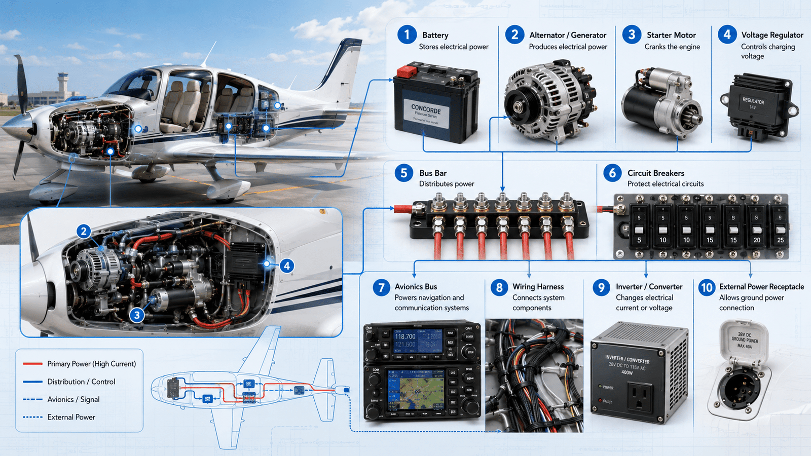
Aircraft electrical system components include generators, generator control units (GCUs), bus bars, transformer-rectifier units, inverters, batteries, and circuit breakers, all working together across AC and DC networks to power flight controls, avionics, and cabin systems. A Boeing 787, for example, generates 1.45 megawatts—enough for roughly 1,000 homes—distributed through over 60 miles of wiring.
A 737NG relies on a 90 kVA engine-driven generator producing approximately 115V at approximately 400Hz, regulated by its GCU before reaching the main distribution bus.
And circuit breaker has a defined role in keeping flight controls, avionics.
And cabin systems alive from engine start to shutdown.
This guide breaks down each major component, explains how they work together across AC and DC networks, and shows where common failure points sit. You’ll get the same framework engineers use during line maintenance, minus the jargon.
Quick Takeaways
- Aircraft power follows six stages: generation, regulation, distribution, protection, load, backup.
- Inspect GCUs regularly to maintain stable approximately 115V/approximately 400Hz output from engine-driven generators.
- Use transformer-rectifier units to convert AC to approximately 28V DC for avionics and batteries.
- Check circuit breakers and current limiters during line maintenance to prevent bus failures.
- Verify bus tie contactors and emergency backups for seamless power transfer during generator loss.
How Electrical Power Flows Through an Aircraft from Generator to Load
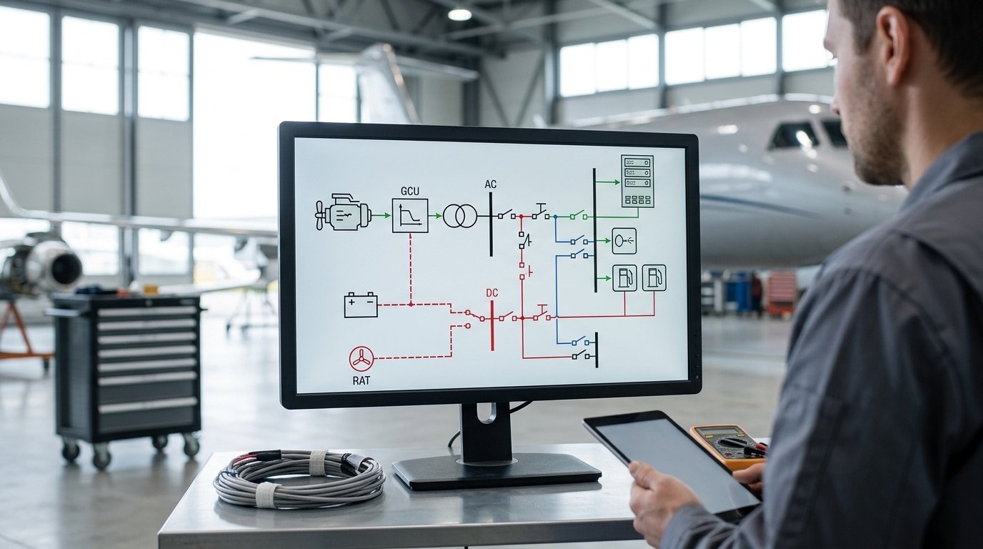
Power moves through an aircraft in a fixed six-stage chain: generation → regulation → distribution bus → protection → load → emergency backup. Every component you’ll meet in this guide sits at exactly one of those stages. Understand the chain, and the role of each part becomes obvious.
Start at the engine accessory gearbox. An engine-driven generator (typically 90 kVA on a Boeing 737NG, per the FAA Aviation Maintenance Technician Handbook) spins out raw three-phase AC. That raw output is unstable, voltage swings with engine RPM.
So it hits stage two: a Generator Control Unit (GCU) trims the field current and locks output to approximately 115V at approximately 400Hz. Clean power then lands on a main AC distribution bus, essentially a copper bar feeding parallel circuits.
Each circuit downstream of the bus passes through a protective device, a thermal circuit breaker, current limiter, or solid-state controller, before reaching its load: fuel pumps, avionics racks, anti-ice heaters, galley ovens.
If the generator quits, bus tie contactors reroute power from the opposite engine within roughly 50 milliseconds. Lose both, and a battery plus static inverter carries flight-critical aircraft electrical system components until the APU spools or a Ram Air Turbine deploys.
Read every later section through this lens: where does this part sit in the chain, and what fails if it dies?
Generators, Alternators and APUs as the Primary Power Sources
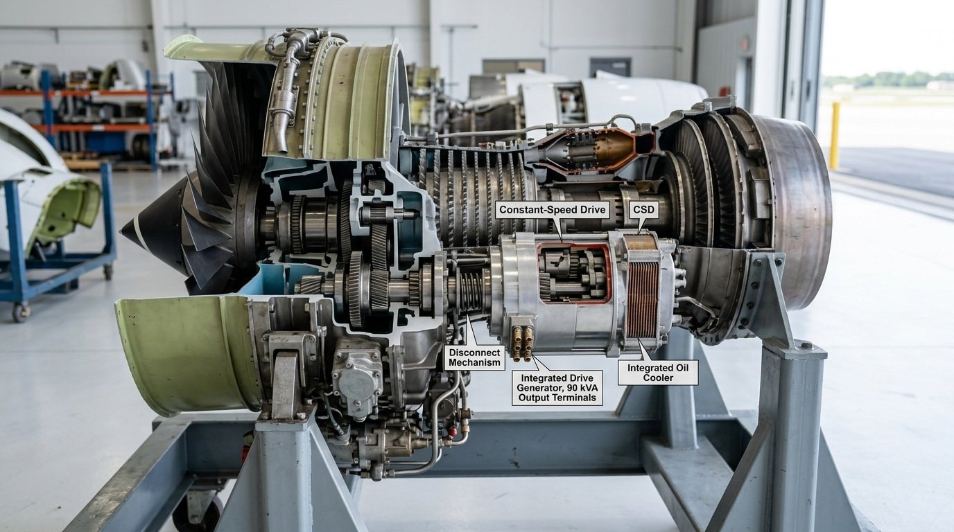
Three source types feed pretty much every certified airframe out there. You’ve got belt or gear-driven alternators on piston singles and twins, plus integrated drive generators (the IDGs) on transport jets.
And then auxiliary power unit (APU) generators for ground work and as a backup in flight. Each one actually produces power in its own way.
And each fails with its own signature pattern, which is really why these three aircraft electrical system components dominate the troubleshooting manuals you’ll find.
On a Cessna 172 or a Cirrus SR22, a 60,100 amp alternator running at approximately 14V or approximately 28V DC handles the entire bus through a field winding that’s excited by the battery. Kill the field.
A worn brush, an open field circuit breaker, or an overvoltage trip, and the alternator drops offline within seconds.
The battery by itself then carries the radios, attitude indication and the gear for roughly 30 minutes before voltage sags below approximately 22V. After that, the avionics start dropping out.
Jets work harder, though. An IDG on a 737 puts out 90 kVA of approximately 115V approximately 400Hz AC power, with a constant-speed drive (or CSD) keeping the generator shaft at exactly approximately 24,000 rpm no matter what the engine N2 is doing.
When oil pressure or temperature climbs past the limits, the crew pulls the IDG disconnect. That’s a one-way mechanical action, and it can only be reset back on the ground.
The lesson from UAL 232’s DC-10 hydraulic loss at Sioux City wasn’t really electrical.
But it basically cemented the design philosophy you see today. Redundant generation, independent buses.
And an APU generator (typically 90 kVA) ready to pick up an essential bus within 45 seconds of an engine-driven source quitting on you.
Voltage Regulators, GCUs and Why Aircraft Run at 14V, 28V, 115V 400Hz, or 270V DC
A Generator Control Unit (GCU) keeps generator output within roughly ±approximately 0.5V of target by adjusting field excitation thousands of times per second. On AC systems it also locks frequency at approximately 400 Hz ±approximately 4 Hz and handles paralleling, fault trip, and bus transfer logic.
Lose the GCU and the generator goes offline within milliseconds, protective by design.
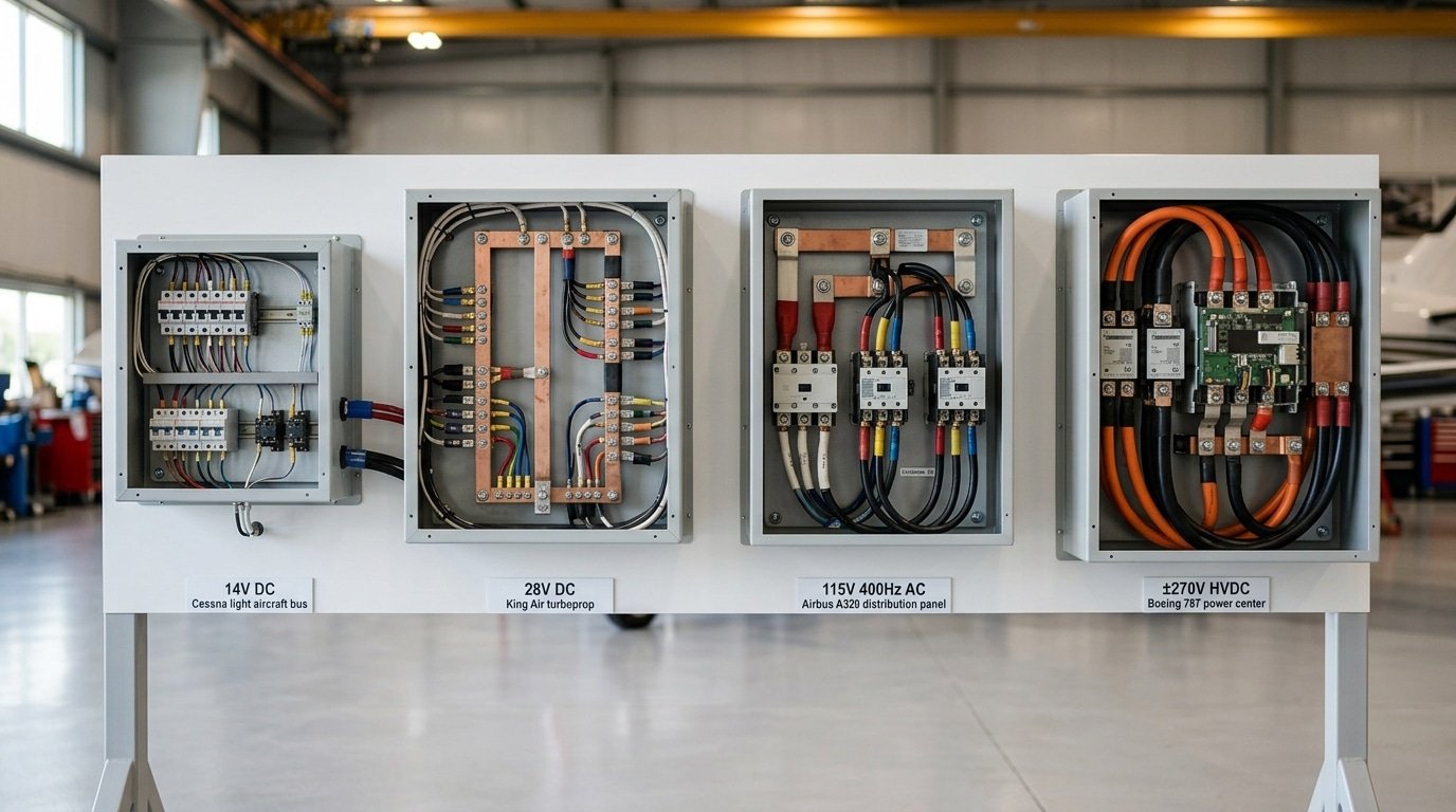
Why four different voltages exist comes down to one trade-off: higher voltage means lighter wire. Doubling voltage cuts current in half for the same power, which lets engineers shrink conductor gauge dramatically.
That’s why Boeing chose ±approximately 270V DC for the 787, the airframe carries roughly 1.45 megawatts of electrical load, and copper weight at approximately 28V would be prohibitive.
| Architecture | Voltage | Typical Wire Gauge (100A feeder) | Representative Aircraft |
|---|---|---|---|
| Light GA, single-engine | approximately 14V DC | AWG 1 | Cessna 172 |
| Twin GA / turboprop / older jets | approximately 28V DC | AWG 4 | King Air 350, Citation CJ3 |
| Transport category | approximately 115V approximately 400Hz AC | AWG 8 | A320, 737NG, 777 |
| More-electric aircraft | ±approximately 270V DC | AWG 12 | Boeing 787, F-35 |
The approximately 400 Hz choice itself is a weight play, transformers and motors at approximately 400 Hz are about three times lighter than approximately 60 Hz equivalents. Across all aircraft electrical system components, voltage selection drives more weight savings than any other single decision.
Distribution Buses, Bus Tie Contactors and Load Shedding Logic
Direct answer: Aircraft electrical system components are arranged in a layered hierarchy of power rails called buses. You have the hot battery bus, the main bus, the essential bus, and the emergency bus.
The whole point of this layered setup? When one power source quits, automatic switches called bus tie contactors quietly rearrange the connections so the flight-critical equipment keeps getting juice. Meanwhile the less important loads are dropped in order of priority.
Each bus sits at its own level of criticality, basically a ranking of how badly the plane needs it:
- Hot battery bus — always powered, even when the battery switch is flipped off. It feeds the clock, the fire extinguisher bottles, and the emergency lights.
- Main bus — the normal generator feed that runs galley ovens, in-flight entertainment, secondary hydraulic systems, and avionics that aren’t life-or-death.
- Essential (or AC ESS) bus — the captain’s primary flight display, one VHF radio, the autopilot, and the fuel pumps. This one keeps running even if a single generator dies.
- Emergency / standby bus — the last bus standing, fed by the battery through a static inverter. Typically good for about 30 minutes of endurance per FAA Part 25 guidance.
Bus Tie Breakers, or BTBs, cross-feed one bus from another when a source goes offline. Here is the catch though. Those contactors are mechanical parts with moving metal.
NTSB report DCA08IA053 documented a Boeing 767 where one of these contactors actually welded itself shut. That stuck part prevented the isolation step after a generator fault, which then cascaded into the loss of two AC buses and forced the crew to divert.
One stuck 50-millisecond relay knocked out roughly 40% of the cabin avionics.
The load shedding logic lives inside the Bus Power Control Unit. It drops the galleys first. Then cabin lighting, then the secondary hydraulic pumps. The essential bus is protected right down to the last amp.

Circuit Breakers, Current Limiters and Protective Relays
Protection devices step in to isolate faults before the wiring actually melts or before electrical arcs end up igniting the insulation around it. Among the aircraft electrical system components really dedicated to keeping things safe, three families generally dominate the conversation: thermal and magnetic circuit breakers (CBs), current limiters.
⚠️ Common mistake: Resetting a tripped circuit breaker more than once during flight, assuming it’s a nuisance trip. This happens because crews underestimate that approximately 90% of repeat trips indicate a genuine short or overload downstream, not a faulty breaker. The fix: follow the one-reset rule per FAA AC 120-80A—if it trips again, isolate the bus and log it for maintenance before further action.
And protective relays which include ground fault interrupters (GFIs) and arc fault circuit breakers (AFCBs).
Thermal CBs work using a bimetallic strip that essentially bends when it’s exposed to sustained heat. They’re slow but really reliable when you’re dealing with overload conditions.
Magnetic CBs, on the other hand, trip in just milliseconds through an electromagnetic coil, catching short circuits before any damage happens further down the line. Many transport aircraft actually mix the two together, using thermal breakers for lighting and galley loads, and magnetic-hydraulic ones for the avionics.
Current limiters are basically heavy-duty fuses (somewhere between 50 and 500A) that get placed between the main buses and the feeders. They essentially sacrifice themselves so they can stop a bus-wide cascade from happening.
And here’s the hard-learned rule: don’t reset a tripped CB more than one time.
And never, ever on a fuel-pump or anti-ice circuit. The Swissair 111 investigation done by the TSB traced the 1998 MD-11 fire back to arcing in some aged Kapton wiring sitting above the cockpit. When you reset, you push current back through a conductor that might still be arcing, which essentially feeds the very fire you’re trying to stop in the first place.
That accident really drove the creation of FAA AC 25-16 and the adoption of AFCBs. These sample current waveforms thousands of times every second so they can detect the chaotic signature of a series arc.
That’s something a thermal CB can completely miss, because the arc current might stay below the trip threshold the whole time.
Batteries, Static Inverters and Ram Air Turbines as Backup Power
When both engines quit, three aircraft electrical system components keep the cockpit alive: the main ship battery, the static inverter, and on larger jets, the Ram Air Turbine (RAT). Each handles a different job, energy storage, DC-to-AC conversion, and emergency generation from airflow.
Battery Chemistry Trade-offs
- Lead-acid (sealed VRLA): Cheap and tolerant, ~approximately 30 Wh/kg. Common on Cessna 172-class GA aircraft. Sulfation kills capacity if left discharged.
- Nickel-Cadmium: The transport-category workhorse. Delivers high current at low temperature and survives 1,000+ deep cycles, but needs scheduled deep-discharge maintenance to avoid memory effect and cell imbalance.
- Lithium-ion: ~approximately 150 Wh/kg — roughly 3× the energy density of Ni-Cad at half the weight, which is why Boeing chose it for the 787.
The 787 Grounding — A Containment Lesson
In January 2013, the FAA grounded the entire 787 fleet for 123 days after two lithium-ion battery thermal runaway events. The NTSB investigation found internal cell shorting propagated cell-to-cell.
Boeing’s fix wasn’t new chemistry, it was a stainless steel containment box with a vent tube routed overboard, plus cell-level spacing and tighter charging limits. The takeaway for designers: assume one cell will fail, then contain it.
Static Inverters and the RAT
A static inverter is a solid-state device that synthesizes approximately 115V approximately 400Hz AC from 28V DC battery power, feeding essential instruments like standby attitude indicators. The Ram Air Turbine deploys into the slipstream as a last resort, on the A320, the RAT supplies roughly 5,10 kW of hydraulic and electric power, enough for flight controls and essential avionics down to about 140 knots.
Wiring, Bonding and Connectors — The Components Pilots Never See
Roughly 40% of the electrical squawks you see in service trace back to chafed wires, corroded pins, or broken bonding straps. Not the boxes drawn on the schematic. These hidden aircraft electrical system components actually fail more often than every generator, generator control unit, and relay put together.
Modern airframes use MIL-W-22759 wire with cross-linked ETFE insulation (the trade name being Tefzel), rated somewhere between 150 and 260°C depending on which suffix you’re looking at. It basically replaced MIL-W-81381 Kapton, which was the aromatic polyimide insulation used heavily across 1970s and 80s fleets, including the F-14 and the early 747s.
Kapton had a real flaw though. Once a small breach lets moisture creep in, the wire can arc-track, which is essentially a self-propagating carbon arc that travels along the wire and lights up adjacent bundles.
The NTSB TWA 800 investigation and the Swissair 111 fire pushed the industry toward composite insulations and much stricter inspection of legacy Kapton harnesses.
Bonding straps are flat tinned-copper braids tying together the airframe, engine mounts, control surfaces, and antennas. They keep resistance below 2.5 milliohms per FAA AC 43.13-1B.
That low resistance really matters. It gives a lightning strike a survivable path and bleeds off the static charge that builds up from friction before it can dump itself through a radio.
Now, connector families worth knowing. There’s MIL-DTL-38999, the circular threaded type and honestly the workhorse of the bunch.
Then MIL-DTL-26482, an older bayonet-style connector. And finally ARINC 600 rack connectors used for avionics line-replaceable units.
One practical tip from experience: always inspect the backshell strain relief and the first six inches of wire leaving any connector. That’s exactly where vibration fatigue and chafing tend to show up first.
How Pilots and Technicians Actually Interact with the System
Pilots touch aircraft electrical system components through three physical interfaces: the overhead panel (or glareshield in light aircraft), the circuit breaker (CB) panel behind the seats, and the engine-start/generator switches on the center pedestal. Everything else hides behind avionics pages.
The Cessna 172 Alternator Failure Drill
Low-voltage light illuminates below roughly 13V on the approximately 28V system. The POH calls for three actions in under 30 seconds: pull the ALT field CB, recycle the master switch (BAT-ALT), then reset the CB.
If voltage stays low, shed non-essential loads, pitot heat, landing light, second comm radio, and land within battery endurance, typically 30 minutes with a healthy battery.
The A320 EMER ELEC CONFIG
When both AC buses fail, the Ram Air Turbine deploys automatically below 100 knots IAS thresholds.
And the ECAM flashes EMER ELEC CONFIG. The crew runs the QRH procedure: confirm GEN 1 and GEN 2 OFF/ON cycle, check ESS BUS powered.
And accept that about 70% of cockpit displays go dark, only PFD 1, ND 1.
And the upper ECAM stay alive.
See the SKYbrary entry on Electrical Emergency Configuration for the full degraded-mode logic.
Technicians, meanwhile, live in the CB panel. A popped breaker is reset exactly once per FAA AC 120-80B, a second pop means the wire use gets opened, not the breaker pushed again.
Frequently Asked Questions About Aircraft Electrical Systems
Why 400Hz instead of 60Hz household power?
At approximately 400Hz, transformers and motors can be roughly 6,7 times lighter than approximately 60Hz equivalents because magnetic core size scales inversely with frequency. On a widebody, that weight saving runs into hundreds of pounds.
The tradeoff is higher transmission losses, which is why approximately 400Hz cables are kept short, a design constraint shaping the bus layouts covered in Section 4.
Can an aircraft fly with a dead battery?
Legally, no, FAR 91.205 and equivalent EASA rules require a functional battery for IFR dispatch. Practically, once generators are online, the aircraft runs fine without battery support, but losing the battery during a dual-generator failure removes your final 30 minutes of essential-bus power.
See the FAA airworthiness guidance for minimum equipment specifics.
What’s the difference between essential and emergency buses?
The essential bus carries flight-critical loads under normal operation and is fed by any available source. The emergency (or “hot battery”) bus is a smaller subset powered directly from the battery, bypassing contactors, it stays live even with every switch off. Section 4 maps the full hierarchy.
Why did the Boeing 787 switch to 270V DC?
Higher voltage cuts current for the same power, so wire gauge shrinks and copper weight drops, critical for the 787’s 1.4 megawatt no-bleed architecture driving electric cabin pressurization. The downside: approximately 270V DC arc faults are harder to extinguish, requiring solid-state contactors instead of mechanical relays.
Key Takeaways and Where to Go Deeper
The power-flow chain is fixed: source → regulation → protection → distribution → load → return. Memorize that sequence and approximately 80% of troubleshooting becomes pattern recognition rather than guesswork.
The three architecture families at a glance
- approximately 14V/approximately 28V DC singles and light twins — alternator, battery, simple bus bar, thermal breakers.
- approximately 115V approximately 400Hz AC transport category — IDG-fed split bus, GCUs, BTBs, TRUs feeding a approximately 28V DC essential bus.
- approximately 270V DC “more-electric” airframes (787, F-35) — variable-frequency starter-generators, solid-state power controllers, no bleed air.
The three failure modes worth memorizing
- Chafed or corroded wiring at clamp points and bulkhead penetrations — the single largest squawk category.
- Generator control unit faults that drop a side off-line and force load shedding onto the battery.
- Connector pin backout and moisture intrusion in Cannon and MS-series plugs, which mimic component failures.
Where to study next
Three sources will take you from reader to practitioner on aircraft electrical system components:
- FAA AC 43.13-1B, Chapter 11 — the canonical reference for wiring repair, bonding resistance limits (under 3 milliohms), and breaker sizing.
- ATA Chapter 24 documentation — every airline manual indexes electrical power under this number.
- The type-specific Aircraft Maintenance Manual (AMM) for whatever airframe you fly or wrench on — schematics there override every textbook.
Bookmark the system diagram from Section 1 and pull it up alongside the AMM next time you trace a fault. Pattern recognition beats memorization every time.