

Copper Laser Welding Parameters for Busbars and Battery Tabs
Copper laser welding parameters must match the material, each layer’s thickness, the joint and the delivered beam. A setting for a thin, nickel-plated copper-to-aluminum tab is not a recipe for a thick copper busbar. Define those conditions first, then qualify a window using traceable specimens, cross-sections, electrical measurements and mechanical tests.

Which Material, Thickness and Joint Are You Welding?
“Copper, 1 mm” is not a complete weld specification. Identify the top and bottom members separately, including coatings, actual fit-up and the interface that must carry current.
| Condition | What to specify | Why the distinction matters |
|---|---|---|
| Copper grade and condition | ETP or oxygen-free grade; temper; supplier lot; surface oxide, roughness and cleaning. | Do not substitute a new grade or surface condition without checking whether the qualified window still applies. |
| Bare or plated material | Base metal, coating metal, coating thickness and tolerance on the laser-facing side and interface. | A nickel-plated copper tab is not an uncoated copper coupon. Plating changes what the beam and molten pool encounter. |
| Each layer’s thickness | Top sheet, bottom sheet or terminal; foil count; individual foil thickness; remaining wall or sensitive region. | The same total stack thickness can hide very different upper-layer melting and lower-interface fusion behavior. |
| Joint and layer order | Lap, butt or foil stack; Cu–Cu, Cu–Al or another combination; laser-facing material; overlap and edge distance. | Reversing Cu–Al order changes initial coupling and mixing. A terminal made of plated steel is a separate joint family. |
| Fit-up and support | Measured gap range, flatness, clamp position, contact force, height datum and backing/support. | Contact and support affect heat flow and collapse. A zero-gap laboratory coupon does not prove a production gap tolerance. |
Thick Copper Busbars Need an Interface and Penetration Target
A thick, stiff busbar changes heat flow and clamping demands. Specify the joined width at the interface and the allowed penetration into the terminal. Increasing power alone may damage the lower member before it solves uneven contact.
Thin Tabs and Foil Stacks Need Layer-by-Layer Checks
Record which foils must be connected and how the stack is compressed. The top layer can melt or cut while lower layers remain unjoined. Inspect the participating layers, not only the seam visible on top.
For a Cu–Al transition, check interface mixing and the product’s electrical and life-test requirements. Keep it separate from a Cu–Cu qualification. IPG’s battery-welding guidance explains how busbar design, tolerances and clamping interact.
How Do Power, Speed, Focus and Wobble Affect Copper Laser Welding?
Power and forward speed do not define a complete setting. Spot size, beam shape, focus and motion decide where the energy acts. Use this matrix to plan trials on the specified joint—not to select values by copper thickness alone.
| Control | What it mainly changes | Risk when too aggressive or unstable | Record in every trial |
|---|---|---|---|
| Power and power profile | Melting onset, penetration and energy available during start, steady state and finish. | Ejection, burn-through, deep terminal penetration, crater or an unstable keyhole. | Commanded and verified output, ramp timing, modulation definition and program revision. |
| Forward speed | Interaction time and nominal energy per unit of seam distance. | Slow travel can increase heat spread; fast travel can leave intermittent fusion. | Speed, acceleration, path length, corner behavior and real motion trace. |
| Spot and beam profile | Power density, seam width and how the melt pool is driven. | A small intense spot may cut a tab; a broad spot may fail to engage the interface. | Measured workplane spot, beam profile, optic, fiber and calibration method. |
| Focus and standoff | Where peak intensity sits relative to the top surface and hidden interface. | Part-height drift can move a stable coupon outside the process window. | Focus offset, datum, height tolerance, sensor result and protective-window condition. |
| Wobble / oscillation | Energy distribution, seam width, melt flow and material mixing. | Excessive dwell or mixing, wider heat spread, changed fade-out and pores. | Pattern, amplitude, frequency, phase, direction, forward speed and actual path logic. |
| Beam offset | Which metal melts first and how much dissimilar material enters the fusion zone. | Too much or too little Cu-Al mixing, edge miss or weak joined area. | Offset from the measured interface, vision datum and tolerance. |
| Clamp, gap and support | Contact heat flow, interface location and stack stability. | Sudden collapse, local ejection, missed interface or crushed cell-adjacent features. | Force/position trace, gap, flatness, support and fixture revision. |
| Surface and shielding | Initial coupling, contamination, oxidation, plume behavior and optic protection. | Variable onset, pores, residue, discoloration or optical contamination. | Plating, oxide/cleaning state, gas/nozzle, flow, extraction and lot identity. |
Why the Same J/mm Can Produce Different Copper Welds
The nominal line-energy index is El = P / v: average incident power P in watts divided by forward speed v in mm/s gives J/mm. It is useful for organizing trials, but it is not absorbed heat input.
Equal J/mm does not mean equal welds. The index leaves out absorption, spot size, focus, beam profile, power ramps and fixture heat flow. With wobble, forward speed also differs from the beam’s actual travel along its oscillating path.
How Do Wavelength, Beam Profile and Laser Mode Change the Parameter Window?
Record the complete laser system, not just its rated wattage. The wavelength affects how copper absorbs light; the spot and beam profile determine where that power is concentrated.
Infrared, Green and Blue Sources Are Different Process Conditions
Near-infrared fiber lasers can weld qualified copper joints. Single-mode optics, wobble and core/ring beam shaping are ways to control coupling and melt behavior. Compare the actual beam configuration, not the fiber-laser label alone.
Green light around 515 nm is absorbed more strongly by room-temperature copper than conventional near-infrared light. That can help welding start consistently. Blue sources around 450 nm offer another visible-wavelength option. For either source, usable power, workplane spot and beam profile still matter.
No wavelength removes the need to control gap, focus or penetration into the lower member. A green- or blue-laser setting cannot be converted to an infrared setting by matching watts. See TRUMPF’s copper-welding guidance and Britten et al.’s blue-laser processing paper.
CW and Pulsed Copper Welding Need Different Parameter Records
For continuous-wave (CW) operation, record delivered power, start/end ramps, forward speed, workplane spot, focus and beam path. If power is modulated, retain the waveform and timing as well as its average value.
For a pulsed source, also record pulse energy, duration, repetition rate, waveform, peak power and overlap. Equal average power does not establish equal peak intensity or interaction time.
Record the beam delivered to the joint: source model, wavelength, mode, delivery fiber, optics, measured spot/profile, focus datum and calibration record. A source power certificate or catalog spot diameter is not a complete workplane measurement.
What Does a Published Copper-to-Aluminum Trial Actually Prove?
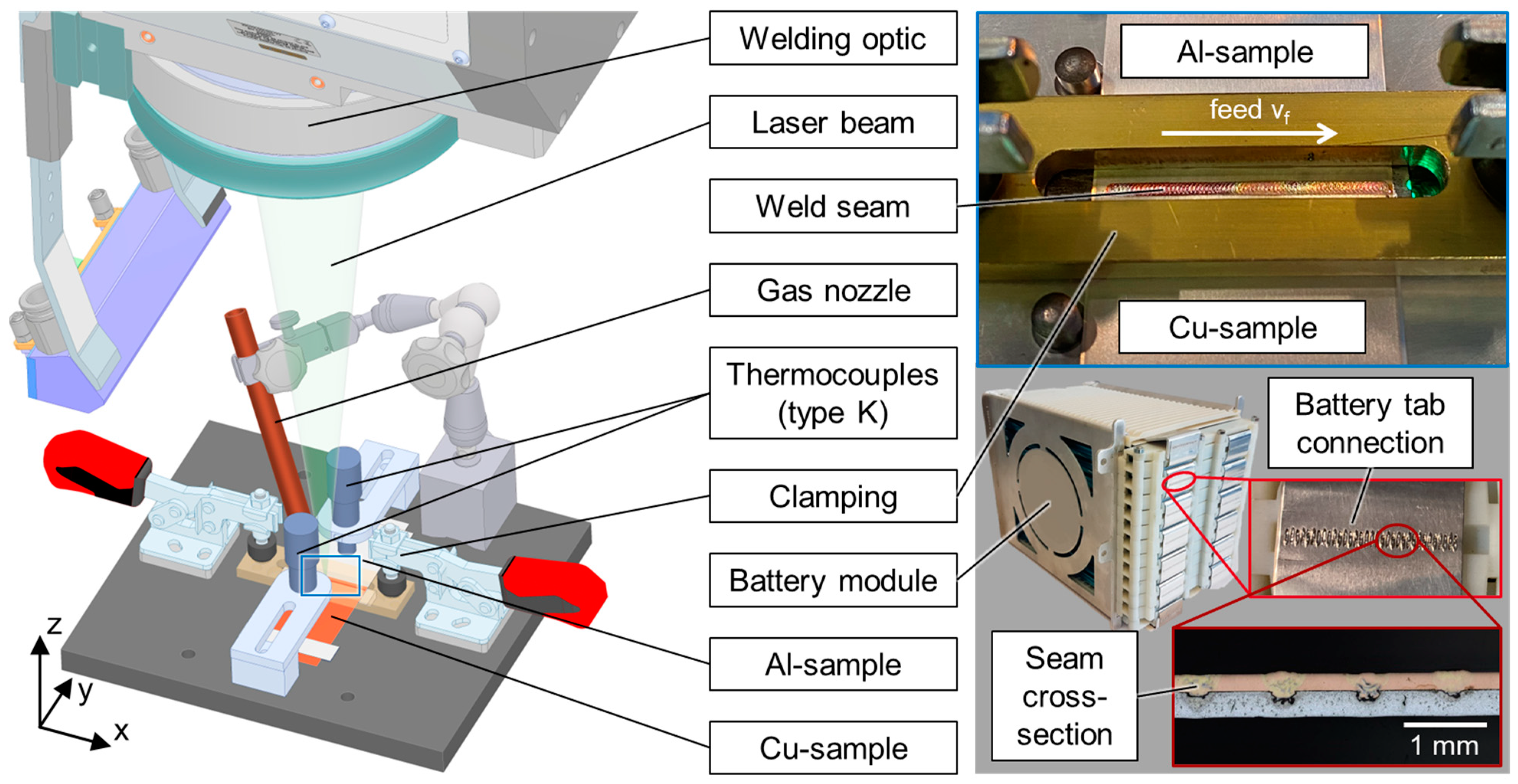
Kaufmann et al. (2023) provide a traceable example—not a universal recipe. The conditions and result below belong to their specific overlap specimens. Read the paper: Section 3, Table 5 and Section 4.7.
| Materials and order | 0.2 mm nickel-plated Cu-ETP above 0.3 mm AlN30; laser incident on copper. |
|---|---|
| Specimen and joint | 55 × 35 mm sheets; 10 mm overlap; zero-gap clamping. |
| Laser and focus | TRUMPF TruDisk 3022; 515 nm CW; measured 342.5 µm top-hat spot; focus on the copper surface. |
| Published setting | Linear stitched strategy; 1,600 W; 500 mm/s. Path geometry and clamping remain part of the setting. |
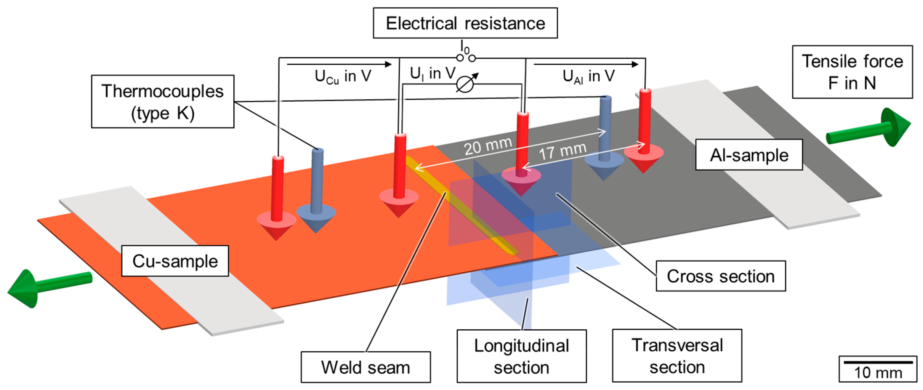
| Resistance method | Four-wire measurement; four specimens per parameter set; ten readings per location at the start, middle and end. |
Reported mean resistance for set #2, the lowest among the studied sets.
Not a customer acceptance limit. Probe geometry, specimen construction and test method belong to this study. Repeated readings are not additional independent weld specimens.
How Do You Qualify a Repeatable Copper Welding Window?
A design of experiments (DOE)—a controlled trial plan—should map stable behavior around the nominal condition. One attractive coupon proves possibility; repeated boundary samples show whether production can stay inside the window.
- Define the joint and pass criteria. Freeze alloy, plating, layer order, thickness, foil count, overlap and the damage-free region. Agree sectional, electrical, mechanical and product-safety requirements before tuning.
- Use representative parts and a controlled fixture. Include real lots, surfaces, flatness and part-height variation. Measure gap, contact, support, clamp force and positioning repeatability.
- Screen a small set of factors. Vary power/profile, speed, focus or spot, and oscillation where used. Hold the other inputs fixed so the result has an identifiable cause.
- Repeat the nominal setting on independent specimens. A single good coupon may be luck. Repeat readings on one coupon do not replace separately welded samples.
- Challenge the candidate window. Test the relevant height, gap, surface, position and material-lot limits. Inspect failures as well as passing joints; do not choose a window from successful samples alone.
- Release the complete process, not just the laser program. Freeze materials, fixture, optics, cleaning, program, inspection and monitoring. Define which changes require another trial or qualification.
Record Enough Detail to Reproduce Each Specimen
Link source and optics, measured output, spot/focus, travel and oscillation program, part lot, surface state, fixture trace, gap/height, gas/extraction and protective-window condition to the sample ID. Record actual conditions alongside commanded settings.
Check Weld Starts, Ends and Corners Separately
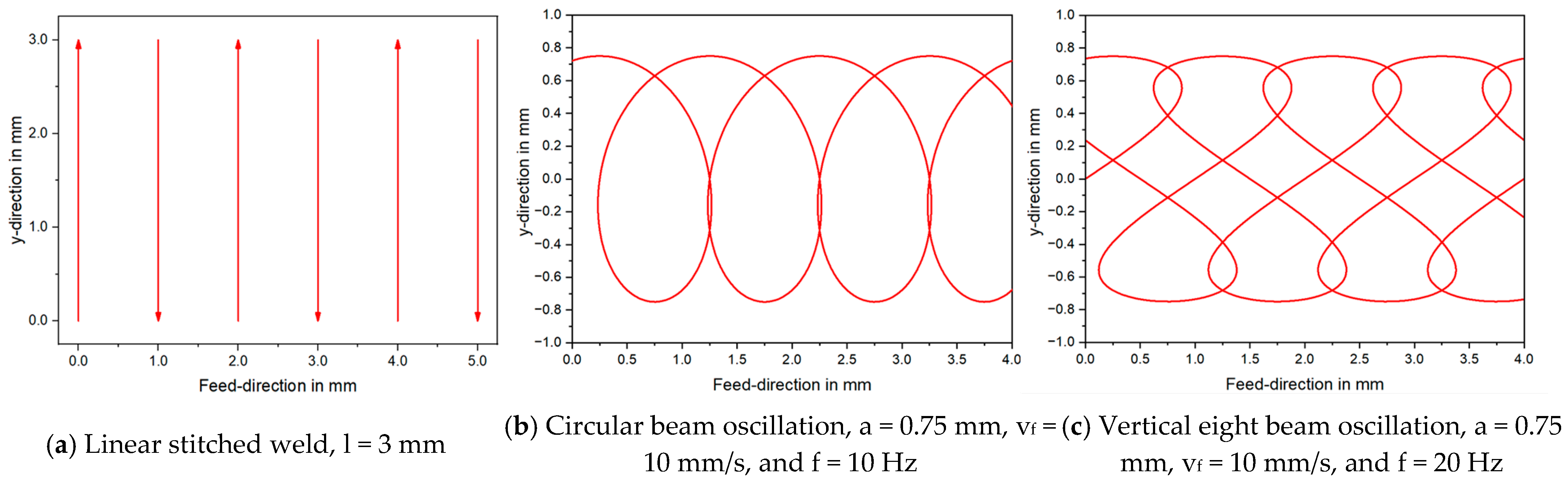
Acceleration, power ramping and oscillation overlap can change local dwell. A steady-state cross-section does not prove that a start, corner or finish is sound. Record the beam path and inspect the relevant zones.
The published study compares linear, circular and figure-eight paths below. The pattern is part of the tested setting: the same forward speed can distribute energy differently along different paths.
How Do You Diagnose Common Copper Laser Weld Defects?
The first corrective action should target the most likely source of variation. Increasing power is rarely a complete diagnosis.
Intermittent Copper Weld Fusion
When fusion appears only in parts of the seam, first check gap, surface condition, part height, optics and delivered output. Compare sections along the path with the clamp record. If those inputs are controlled, test power profile, focus and speed together rather than increasing power alone.
Spatter or Metal Expulsion Near Battery Features
Ejected metal can leave pits or underfill and threaten nearby cell features. Check contact, local dwell, the start ramp and focus. Compare start, steady-state and end sections with available process signals; then test a less aggressive power profile or a different energy path.
Thin Copper Tab or Foil Cut-Through
Check spot size, support, height and local dwell when the upper layer cuts before the lower interface joins. Section the stack layer by layer. Test reduced intensity or dwell and improved support, while confirming that all required layers still connect.
A Good-Looking Copper Weld with High Resistance
A continuous surface bead can hide poor joined area, oxide, cracks or missed foil layers. Pair a fixed-method four-wire test with cross-sections. Correct the current path and interface integrity, not just the bead’s appearance.
What Specimen Records and Acceptance Results Should a Supplier Provide?
Agree the acceptance criteria before tuning. Each result must identify the specimen, method, measured value and applicable limit. “Looks good” and “low resistance” are not complete acceptance records.
| Evidence | Method and conditions | Result to record | Acceptance basis |
|---|---|---|---|
| Fusion and penetration | Prepared cross-sections at defined start, steady-state and end locations; include each required interface. | Specimen ID; scaled images; joined width and depth in mm; defects; remaining wall; foil engagement. | Drawing/test-plan requirements for bonded area, penetration limits and prohibited defects. |
| Electrical resistance | Four-wire method; fixed probe locations, current, specimen temperature and measurement sequence. | Individual values in µΩ or mΩ; spread; instrument/calibration; uncertainty where relevant. | Product-specific voltage-drop or resistance limit for the defined measurement path. |
| Mechanical integrity | Specified shear, peel or pull method; fixed fixture, load direction and test rate. | Load in N; displacement where needed; failure location/mode; photos linked to specimen ID. | Approved minimum or other service-related criterion. Different loading methods are not interchangeable. |
| Heat-sensitive features | Defined sensor position, response and time history on the actual support and thermal path. | Temperature in °C; time trace; penetration clearance; seal/insulation inspection. | Cell/component supplier limits and the product safety plan—not a generic temperature copied from a coupon paper. |
| Function and reliability | Applicable current duty, thermal/mechanical cycling, isolation or leak tests after welding. | Test conditions, cycle count, before/after measurements and failure observations. | The intended service and product qualification requirements. |
| Repeatability | Nominal repeats and deliberate boundary trials across relevant lots, fit-up and optical condition. | All specimen results, including failures; tested factor range; separate independent samples from repeat readings. | Approved sampling plan and demonstrated window. One passing coupon does not establish production robustness. |
Link the Weld Specimen, Process Record and Acceptance Result
Use one specimen ID across the drawing, material lot, coating record, fixture revision, laser program, output/spot check and test files. Choose sample counts for the relevant failure modes and qualification route; no universal coupon count approves every busbar, foil stack or cell connection.
Report each criterion as pass, fail or not demonstrated, with its limit and measured result. Passing resistance with missing penetration or strength evidence is not an overall pass. A feasibility trial also does not replace the sampling, reliability and change-control requirements for production release.
Use a Fixed Four-Wire Method for Low-Resistance Welds
One lead pair supplies current and another senses voltage, reducing test-lead error. Keep probe locations, temperature and current fixed. Control self-heating and thermoelectric offsets with a suitable measurement procedure, which may include current reversal.
The reading includes the material between the sense probes. Changing probe spacing or specimen width can change resistance without changing weld quality. Define that measurement path before comparing samples. Keithley handbook, Chapter 3.
How Do You Keep Copper Weld Quality Stable in Production?
A qualified window only remains useful while its inputs stay controlled. Define what operators must check, what triggers a stop and which changes require requalification.
Control Material Lots, Gap and Fixture Wear
Track grade, temper, plating, surface state and supplier lot. Maintain the fixture’s contact, force, height datum and support. Cleaning or wear can change fit-up even when the drawing and program have not changed.
Lock Optics and Programs, Then Verify Quality
Record protective-window service, focus/output checks and program revisions. Keep power profile, path, speed, offset and wobble under change control. Correlate any monitoring signal with section, resistance and mechanical results; define sampling, alarm and response rules before production.
Include Laser Safety and Battery Handling in the Cell Design
Assess direct and reflected beam paths, enclosures, interlocks, access and maintenance states. Select extraction for the actual metals and coatings. For cell connections, plan electrical isolation, heat-sensitive features, damaged-cell handling, quarantine and fire response. A passing weld coupon does not establish installation safety. OSHA laser-hazard guidance.
What Should You Send a Supplier for a Copper Welding Trial?
Send enough information to reproduce the joint and judge the result. A material name and target thickness are not enough to choose a qualified laser configuration.
- Joint drawing and representative samples: every alloy, temper, plating and thickness; foil count, layer order, overlap, accessible weld side and gap range.
- Product limits: required joined area, allowed penetration, nearby seals or cell features, thermal limits and isolation state.
- Service and acceptance requirements: current duty, the defined resistance/voltage-drop method, mechanical load direction, cycling and reliability criteria.
- Existing equipment and workholding: wavelength, mode, source, optics, measured spot/focus, program, datum, support and clamp concept.
- Trial history and production variation: specimen records, passing and failing results, material lots, repeats and boundary conditions already tested.
- Installed-cell scope: cycle time, loading, safety enclosure, extraction, utilities, monitoring, sampling, service and change-control responsibilities.
Use these guides to define the material, joint geometry and parameter controls before requesting a representative-part trial.
Send Oceanplayer Laser the drawing, layer stack, representative samples and acceptance requirements. Start with the joint and test plan, then evaluate the laser configuration. Do not use a thin-tab research setting as a purchase specification for a different busbar or battery connection.
Sources for the Specimen Data and Test Methods
- Kaufmann et al., Materials 16 (2023), 1069 — specimen/setup in Section 3; settings in Table 5; resistance results in Section 4.7. DOI: 10.3390/ma16031069. Figures 2–4: Kaufmann et al., CC BY 4.0; resized.
- Britten et al., Procedia CIRP 94 (2020), 592–595 — blue high-power laser processing in e-mobility.
- TRUMPF: Welding copper — green coupling, infrared beam shaping and wobble options.
- IPG: EV battery laser-welding considerations — clamping, positioning and busbar design.
- Keithley Low Level Measurements Handbook, Chapter 3 — four-wire measurements and low-resistance error control.
- ISO 13919-2:2021 — imperfection-quality scope and its fitness-for-purpose limitation.
- OSHA Technical Manual: Laser Hazards — optical hazards and controls.
- Busbar installation photograph: ToT89, Wikimedia Commons, CC BY-SA 4.0; cropped.