

Wire Feeding vs No Wire Feeding Laser Welding: Which Is Better?
No-wire, or autogenous, laser welding is usually the cleaner starting route when edges fit tightly and the base metals can produce the required weld chemistry and bead shape. Add filler wire when the joint needs controlled added metal—for gap bridging, fillet volume, underfill correction or metallurgical modification.
Neither method is universally stronger, faster or cheaper. The better process is the one that passes the required inspection while remaining stable across the real joint gap, part tolerance, material lot, operator motion and production cycle.
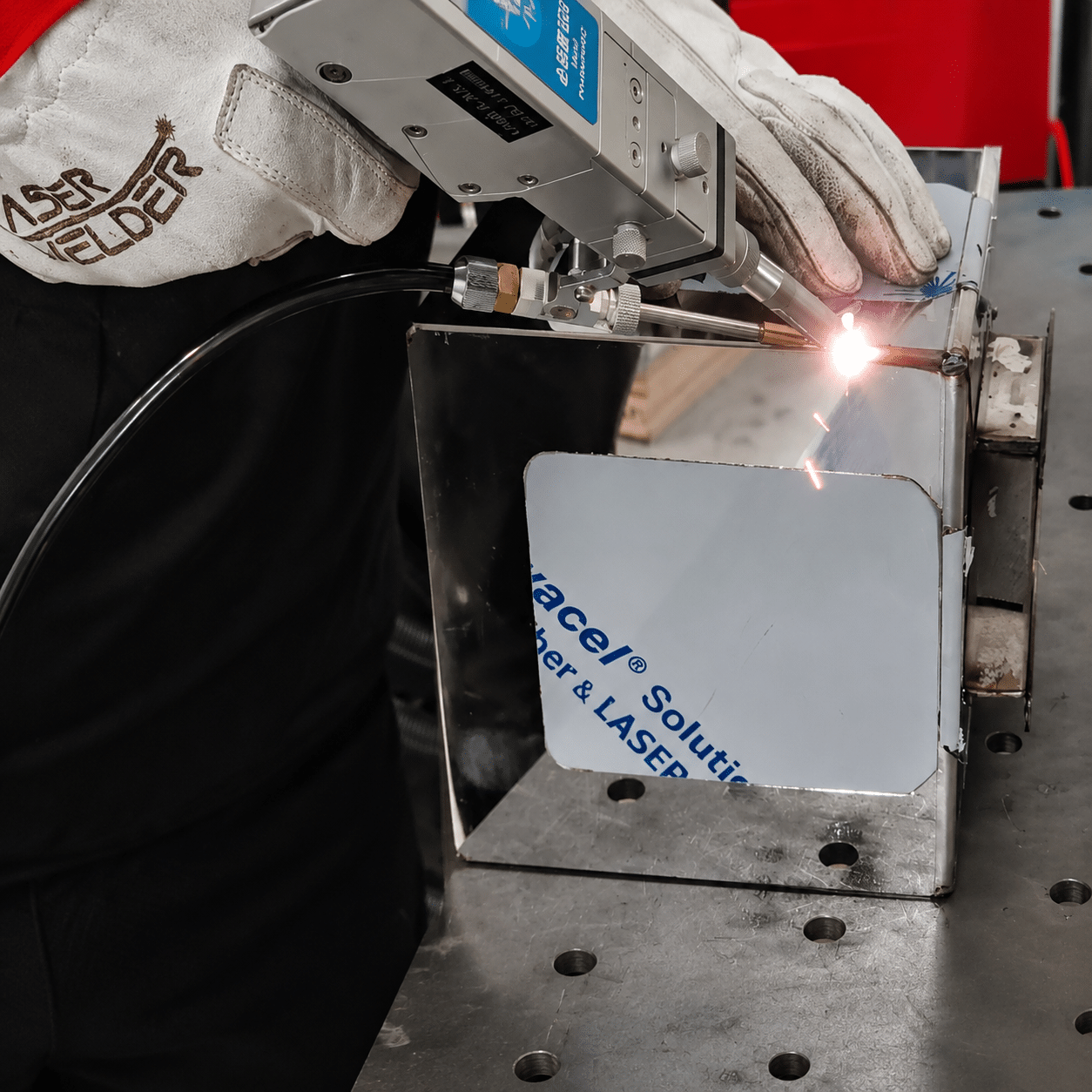 Choose from the joint—not the accessory list
The beam, wire, travel path, joint and shielding must meet in one repeatable melt pool.
Choose wire only when it solves a defined joint problem.
A process that needs no filler has fewer interacting variables and consumes no wire. A process that needs added volume or chemistry should not be forced to run autogenously merely to simplify the equipment.
Base-metal edges provide enough volume, the alloy combination is suitable, and a narrow flush seam is desired.
The joint has a controlled gap, needs fillet reinforcement, risks underfill or benefits from a qualified filler composition.
Fit-up varies by lot, appearance and strength compete, or beam oscillation may replace some—but not all—filler demand.
Large or moving gaps, poor aim, dirty surfaces and incompatible chemistry still require joint redesign or another process.
Wire feeding and autogenous laser welding solve different constraints.
The comparison below avoids universal speed, penetration and thickness numbers. Those depend on material, joint, focal conditions, power density, weld mode, equipment and acceptance criteria.
| Decision factor | No wire / autogenous | With filler wire | What to verify |
|---|---|---|---|
| Metal source | Only the base materials form the weld pool. | Base metal and a metered filler wire form the weld pool. | Required cross-section, reinforcement, dilution and chemistry. |
| Fit-up demand | Usually requires tighter edge position and gap control because no added volume replaces missing metal. | Can increase tolerance to a qualified gap or edge shortage, but the wire must enter the pool consistently. | Minimum, nominal and maximum production gap—not one ideal coupon. |
| Metallurgy | Weld chemistry comes from the base materials and their dilution. | Filler can modify composition, crack sensitivity, corrosion behavior and color match. | Exact alloys, filler classification, dilution and service condition. |
| Bead geometry | Well suited to narrow, flush or low-reinforcement seams when material volume is sufficient. | Useful when a fillet, crown, edge build-up or underfill compensation is required. | Cross-section and throat—not appearance alone. |
| Process variables | Laser power, speed, focus, beam motion, aim, shielding, surface and fixture dominate. | Adds wire alloy, diameter, feed speed, angle, position, stick-out, drive rolls, liner and synchronization. | Repeatability through starts, corners, stops and torch orientation changes. |
| Consumables | No filler-wire purchase, storage or path maintenance. | Requires matched wire, tips, rolls/liners and inventory control. | Total cost per accepted part, including fit-up and rework. |
| Potential speed | Often faster when the joint is already laser-ready, because there is no wire-melting or placement limit. | May require lower travel speed to incorporate the necessary filler volume; can still improve total throughput if it prevents rejects or upstream precision work. | Accepted parts per shift, not maximum travel speed. |
| Best starting point | Precision sheet, sealed components, tightly fixtured butt/lap seams and repeat assemblies. | Controlled gaps, fillet volume, crack-sensitive alloys, dissimilar joints and repair/build-up requirements. | Representative sample test with the actual joint and acceptance method. |
What changes when filler wire enters the laser weld pool?
The laser remains the primary heat source in both routes. Wire does not replace control of coupling, penetration, shielding, surface condition or joint tracking; it adds mass and chemistry that must be melted, positioned and mixed.
No filler wire
The beam melts material from one or both joint edges. The molten edges flow together and solidify as the seam.
- Primary advantageFewer synchronized variables and no filler consumption.
- Primary demandPrecise aim, contact or controlled gap, and enough base-metal volume.
- Typical geometryButt, lap, edge and conduction-mode cosmetic seams designed for laser access.
- Main failure modesUnderfill, lack of fusion, beam passing through a gap, misalignment and base-alloy cracking.
Wire feeding
A feeder pushes a specified wire through a liner and guide toward the leading or trailing region of the laser-generated melt pool.
- Primary advantageAdds controlled volume and can alter weld-metal chemistry.
- Primary demandStable feed, correct wire aim and synchronized wire/beam/travel motion.
- Typical geometryGap-prone butt joints, fillets, visible corners, dissimilar combinations and crack-control trials.
- Main failure modesCold wire, incomplete incorporation, feeding pulsation, excess reinforcement, spatter and inconsistent dilution.
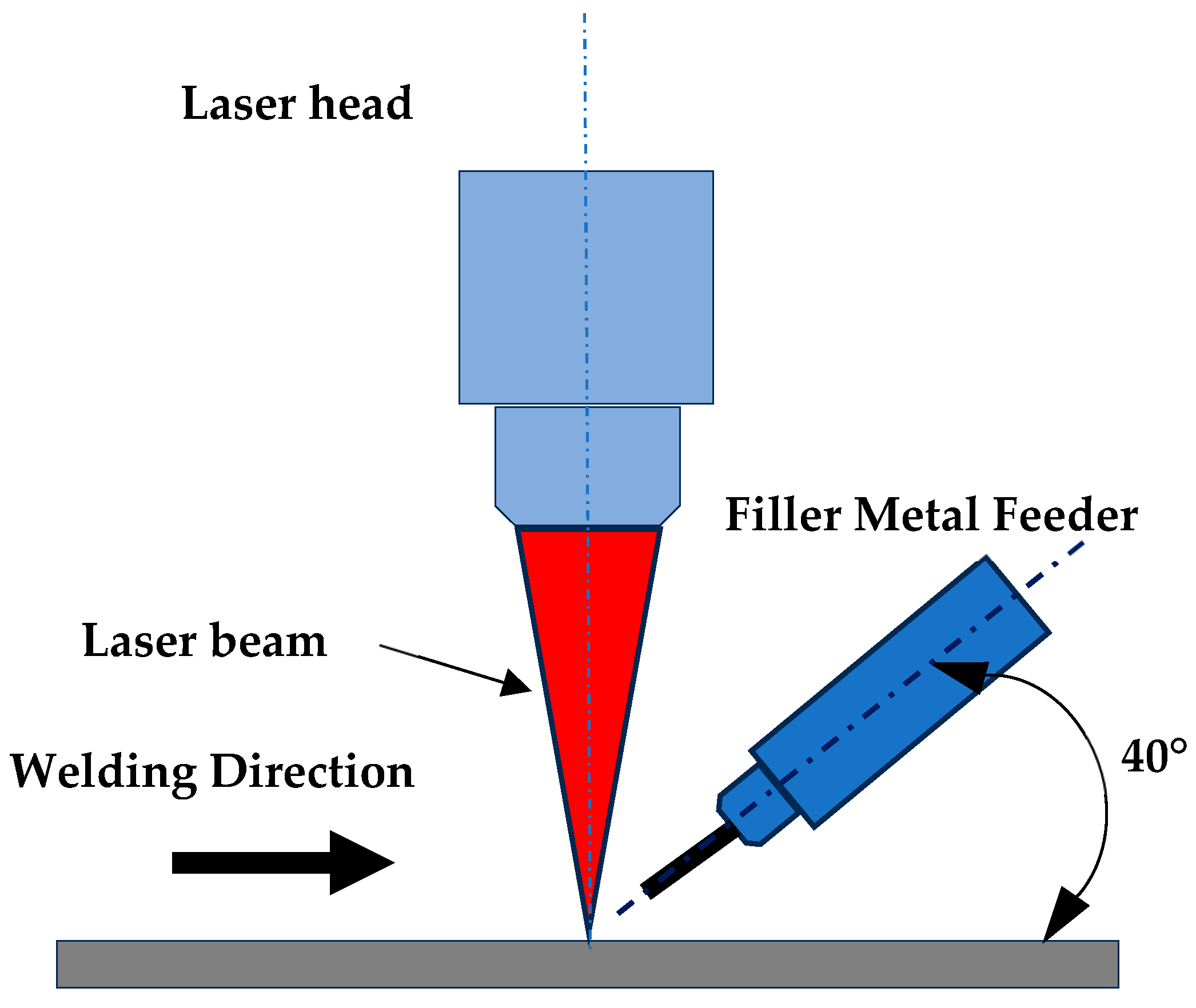
Wire position is part of the energy balance.
The wire must intersect a region that can melt it without blocking the beam or chilling the pool. Feed angle, approach direction, beam position, spot size, travel and joint geometry determine whether the filler is incorporated smoothly.
A peer-reviewed AA7075 study used controlled laser power, travel speed, wire speed, shielding and wire angle to examine how different fillers changed cracking behavior. That experiment demonstrates the principle—not a universal setting for handheld systems.
Practical consequence: copy the method of controlled testing, not the paper's parameter numbers.
Figure adapted from Alkhabbat et al., Metals 2023, 13, 1704, CC BY 4.0.Autogenous laser welding depends on the joint supplying enough molten base metal to create the required cross-section. If a butt-joint gap becomes large relative to the focused spot and available edge volume, energy can pass through the opening or the edges can melt back without bridging. The result may be underfill, intermittent fusion, concavity or an open seam.
Filler wire can supply missing volume, but its gap-bridging capability is not unlimited. The wire must enter the molten region at a repeatable location. If the gap moves, the seam wanders or the wire approaches at an unstable angle, the filler may dive through the joint, strike a cold edge, ball up, deflect the beam or create an oversized crown.
Why a single “maximum gap” number is unsafe
Published gap values belong to a specific joint, thickness, beam diameter, process mode, wire, power, speed and acceptance criterion. For example, a TWI comparison on 8 mm C-Mn steel found very different gap behavior among autogenous laser, laser with filler wire and hybrid laser-MAG routes. That result is useful evidence that filler can expand tolerance; it is not a handheld-laser specification for every metal.
When fixing the part is better than adding wire
- The joint moves during welding because the fixture is weak.
- Edge quality varies because cutting or bending is uncontrolled.
- The seam is inaccessible to both the beam and the wire guide.
- The gap exceeds the amount of metal that can be incorporated without losing the required bead or heat input.
- The added wire hides—but does not remove—misalignment or lack of fusion.
Improving upstream cutting, forming, seam location or fixturing may create a faster and more stable autogenous process. Conversely, if part redesign is impossible and a controlled filler route meets the drawing, wire feeding may reduce total manufacturing cost even when the welding station is more complex.
A stable wire feed requires more than setting a speed number.

Spool → rolls → liner → guide → weld pool.
Every part of the route can change the delivered feed. The spool must unwind without overrun; drive rolls must match wire material and diameter; pressure must transmit motion without crushing or shaving; the liner must be clean and appropriately sized; the guide tip must place the wire without excessive drag.
Soft aluminum wire is especially sensitive to deformation and conduit resistance. Steel and stainless wire tolerate different roll geometries and pressures. Follow the feeder and filler documentation rather than assuming one roll, liner or tip fits every spool.
- Keep the conduit as straight and gently curved as practical.
- Confirm steady jog/retract motion before enabling laser emission.
- Set the wire-to-pool position at the real working angle and standoff.
- Check starts and stops; steady-state feeding alone is not enough.
- Replace worn consumables before compensating with more pressure.
Do not choose wire by diameter alone.
Diameter controls delivery geometry and volume rate. Alloy classification controls what enters the weld metal. A wire that feeds smoothly can still produce the wrong strength, corrosion response, color, crack sensitivity or service behavior.
Base-metal combination
Identify both materials, grades, conditions and coatings. Similar-looking steels or aluminum alloys can demand different filler strategies.
Document exact specifications—not “stainless,” “mild steel” or “aluminum.”Dilution
The final weld-metal chemistry comes from the filler plus the portion of each base metal that melts and mixes. Wire classification alone does not equal final chemistry.
Use a cross-section and, where necessary, composition analysis.Cracking susceptibility
Qualified filler can shift weld composition away from a crack-sensitive range. The benefit depends on adequate and uniform mixing through the weld depth.
Inspect the root and internal fusion zone, not only the top bead.Service requirements
Strength, ductility, corrosion, temperature, electrical performance, food contact, pressure and appearance may constrain the filler choice.
Let the drawing and service environment define acceptance.Color and finishing
Filler dilution can change color after polishing, anodizing or chemical treatment. A mechanically acceptable bead may remain visually unacceptable.
Finish and expose the qualification coupon exactly like production.Wire condition
Rust, oil, moisture, oxide, dirt or inconsistent cast can introduce porosity, unstable feeding and contamination.
Control storage, spool handling, lot traceability and cleanliness.How the two routes fail—and what to inspect first.
A smooth bead can conceal lack of fusion, root underfill, internal porosity or cracking. Diagnose the mechanism before changing power, wire speed or wobble.
Missing volume or missing fusion
- Concave or sunken beadThe joint may not supply enough molten volume, or excessive vaporization may remove metal.
- Intermittent seamGap, aim, focus, surface condition or motion may be outside the process window.
- One-sided fusionThe beam may track one edge while failing to wet the other.
- Hot crackingBase-alloy chemistry, weld shape and restraint may be unsuitable for autogenous welding.
Unmelted, misplaced or excessive filler
- Wire balls or pushes the poolWire placement, feed/travel balance or available energy may be wrong.
- Irregular reinforcementFeed pulsation, conduit drag, torch angle or operator travel may be inconsistent.
- Cold lap or incomplete mixingFiller may sit on the surface without sufficient base-metal fusion.
- Spatter or wire burnbackStart timing, guide position, heat balance or stopping sequence may be unstable.

A clean seam is valuable—but acceptance depends on function.
Laser-welded sealed components show why autogenous processing can be attractive: a narrow seam, localized heat and no filler inventory. Yet the real requirement may be hermeticity, dimensional stability or fatigue life rather than visual appearance.
For critical production, define the inspection method before optimizing the bead. Macrosection, leak testing, tensile/shear testing, bend testing, radiography, CT, metallography or application-specific NDT may be appropriate.
Use the same acceptance method when comparing wire and no-wire trials.
Image: Phiarc / Wikimedia Commons, CC BY-SA 4.0.Which route is faster—and which one costs less?
An autogenous process often has the highest speed potential when the joint is stable because all laser energy can be managed around melting the base material and forming the required penetration. There is no additional wire mass to melt, no spool change and no wire path to maintain.
Wire feeding may require a different power/travel balance and can reduce peak travel speed when substantial filler volume must be incorporated. But it can improve total economics if it bridges a qualified tolerance, prevents underfill, reduces edge preparation, changes crack-sensitive chemistry or avoids rejects.
Cost elements for no-wire laser welding
- More precise cutting, bending, joint tracking or fixturing may be required.
- No filler-wire or wire-path consumable cost.
- Potentially shorter changeover and fewer feed-related stoppages.
- Rework risk rises if real fit-up exceeds the autogenous window.
Cost elements for wire-fed laser welding
- Wire, guide tips, drive rolls/liners, storage and traceability.
- Setup and maintenance of feed position, pressure, path and timing.
- Potential reduction in upstream precision work or gap-related rejects.
- Possible finishing cost if excessive reinforcement is created.
The correct metric is cost per accepted part at the target output. A “slower” wire-fed seam can win if it eliminates repeated failures; a “faster” autogenous seam can win when part design already provides excellent fit-up.
Typical starting routes by production scenario.
Tight, visible corner seam
Start autogenously when bending and fixturing produce continuous contact and the base alloy is suitable.
- Prioritize low distortion and appearance
- Map corner radius and aim position
- Add wire only if underfill or gap remains
Gap-prone butt joint
Compare improved fit-up against a wire-assisted route. Do not assume filler can absorb the complete tolerance stack.
- Measure the real gap distribution
- Test wire at boundary conditions
- Inspect both edges and the root
Required throat or reinforcement
Wire may be necessary when the drawing requires more weld-metal volume than the melted edges can supply.
- Define throat and leg dimensions
- Control dilution and bead shape
- Verify strength on real geometry
Cracking-sensitive composition
A qualified filler route may alter weld chemistry, but the exact alloy, temper, dilution and service strength must be evaluated.
- Compare filler candidates
- Section the full depth
- Check HAZ and as-welded properties
Narrow seam with strict leak target
Autogenous processing is attractive when parts can be machined and fixtured tightly, reducing contamination and added variables.
- Define leak acceptance first
- Validate starts and overlap zones
- Use internal inspection as required
Material must be restored
Wire feeding becomes a deposition task when missing material must be rebuilt rather than merely joined.
- Separate joining from cladding goals
- Plan machining allowance
- Control heat accumulation and layers
Thick sections can be welded without filler—and thin parts can need it.
Autogenous deep-penetration laser welding can join substantial sections when joint preparation, power density and process stability support it. Conversely, a thin corner can need filler if a visible radius, designed fillet or gap compensation is required.
Do not map “thick = wire” and “thin = no wire.” Start with required joint cross-section, alloy behavior and actual fit-up.
- Thickness affects energy and penetration strategy.
- Gap affects available metal volume and beam interaction.
- Joint design affects where filler can be delivered.
- Acceptance affects whether added reinforcement is useful or harmful.

Should your first trial use wire or no wire?
This planning screen organizes the first coupon route. It does not issue a welding procedure, filler classification or guaranteed gap tolerance.
Describe the joint
Choose the closest production condition—not the best hand-picked sample.
The current joint description favors an autogenous trial because fit-up and base-metal volume appear controlled.
- Verify gap and seam position across repeated parts
- Develop power, speed, focus and beam-motion window
- Inspect the full cross-section before approving appearance
A qualification plan that compares both routes fairly.
Define the joint
Record both base grades, thickness, coating, joint drawing, access, gap range and fixture condition.
Define acceptance
Specify appearance, penetration, throat, strength, leak, distortion and permissible defects before welding.
Control surfaces
Use the same preparation, gas condition, handling and time-to-weld for comparable trials.
Map no-wire window
Test beam aim, power, speed, focus and motion at real fit-up boundaries when autogenous welding is viable.
Add wire deliberately
Select filler from metallurgy and service needs, then qualify diameter, position, speed and timing.
Inspect internally
Section starts, steady travel, corners and stops; add NDT or mechanical/leak tests required by the product.
Challenge variation
Use different part lots, gaps, orientations, operators and production temperatures—not one ideal coupon.
Compare economics
Calculate accepted parts per shift, upstream preparation, consumables, maintenance, inspection and rework.
Choose the process from evidence, not assumptions.
Send Oceanplayer the materials, thickness, joint drawing, measured gap range, required bead or throat, target output and acceptance method. We can plan a comparison between autogenous, wobble and wire-assisted laser welding using representative samples.
Related laser-welding resources.
Laser Welder With Wire Feeder
Review wire-assisted system architecture and core buying considerations.
Engineering toolWire Feed Speed Calculator
Estimate filler delivery relationships before representative coupon tests.
Setup guideAdjust Wire-Feeding Speed
Balance filler volume, travel, placement and the qualified bead target.
Engineering toolWelding Heat Input Calculator
Compare power and speed with a transparent planning calculation.
Wire feeding vs no wire feeding laser welding FAQ.
Is laser welding better with wire or without wire?
No method is universally better. No-wire laser welding is usually simpler and potentially faster for tightly fitted, compatible parts. Wire feeding is valuable when the joint needs added volume, controlled gap bridging, a fillet, underfill correction or metallurgical modification.
Is a wire-fed laser weld always stronger?
No. Strength depends on fusion, penetration, joint cross-section, dilution, defects, base and filler metallurgy, heat-affected-zone behavior and service loading. Adding the wrong wire or failing to incorporate it can reduce quality.
Can no-wire laser welding produce deep penetration?
Yes. Autogenous laser welding can operate in keyhole mode and produce deep, narrow welds. Penetration capability depends on material, joint, available power density, focus, speed, beam profile and process stability—not on filler presence alone.
Does filler wire allow laser welding across any gap?
No. Wire expands gap tolerance only within a qualified range. The beam, wire and both joint edges must interact consistently. Large, moving or misaligned gaps may require better cutting, forming, fixturing, joint redesign or another welding process.
When is autogenous laser welding the best starting point?
Start without wire when fit-up is tight and repeatable, the base materials provide suitable weld chemistry and sufficient volume, the required seam is narrow or flush, and inspection confirms fusion and performance.
When should I start laser welding with filler wire?
Start with wire when the drawing requires added throat or reinforcement, the real joint has a controlled gap or edge shortage, autogenous trials show underfill, or a qualified filler is needed to modify crack sensitivity or weld chemistry.
Can beam wobble replace filler wire?
Beam oscillation can widen the effective melt zone and improve tolerance to some joint conditions, but it does not create new metal. It may reduce filler demand in a specific joint; it cannot replace required weld volume or metallurgy.
How do I choose filler-wire diameter?
Choose a diameter supported by the welding head, feeder, rolls, liner and guide tips, then confirm that its controllable delivery range matches the required filler volume. Diameter alone does not select alloy, feed speed or gap capability.
How do I choose filler-wire alloy?
Use the exact base metals, dilution, strength, ductility, corrosion, temperature, finishing and applicable procedure requirements. Follow filler-metal manufacturer guidance and qualify the final weld rather than choosing by a generic material label.
Does wire feeding make handheld laser welding harder?
It adds setup and coordination: wire path, feed speed, guide position, torch angle and start/stop timing. Once correctly configured it can make a suitable gap-prone joint easier to produce, but it does not remove the need for training and a qualified process.
Which process is cheaper?
No-wire welding avoids filler and feeder maintenance, but may require more precise parts and fixtures. Wire feeding adds consumable and setup costs, yet may reduce reject, rework or upstream tolerance costs. Compare total cost per accepted part.
Can I use the same laser parameters after turning on the wire feeder?
Do not assume so. The filler introduces mass, changes heat distribution and may alter travel or beam-motion needs. Develop and qualify a wire-assisted parameter window using representative samples.
How should wire and no-wire trials be compared?
Use the same materials, surface preparation, joint geometry, gap boundaries and acceptance criteria. Record settings, section the welds and perform the mechanical, leak, NDT or appearance tests required by the product.
What information should I send for a process recommendation?
Provide base-material grades and coatings, thicknesses, joint drawing, measured gap range, desired bead or throat, filler candidates, welding orientation, target cycle, photos and the required inspection or acceptance standard.