

Casting vs Forging vs Machining: How Metal Parts Are Made
Casting fills a mold with molten metal. Forging reshapes solid metal with compressive force. Machining removes material from stock or a near-net blank. The best route is not a process label—it is the complete path that satisfies function, geometry, quantity, quality evidence and total cost.


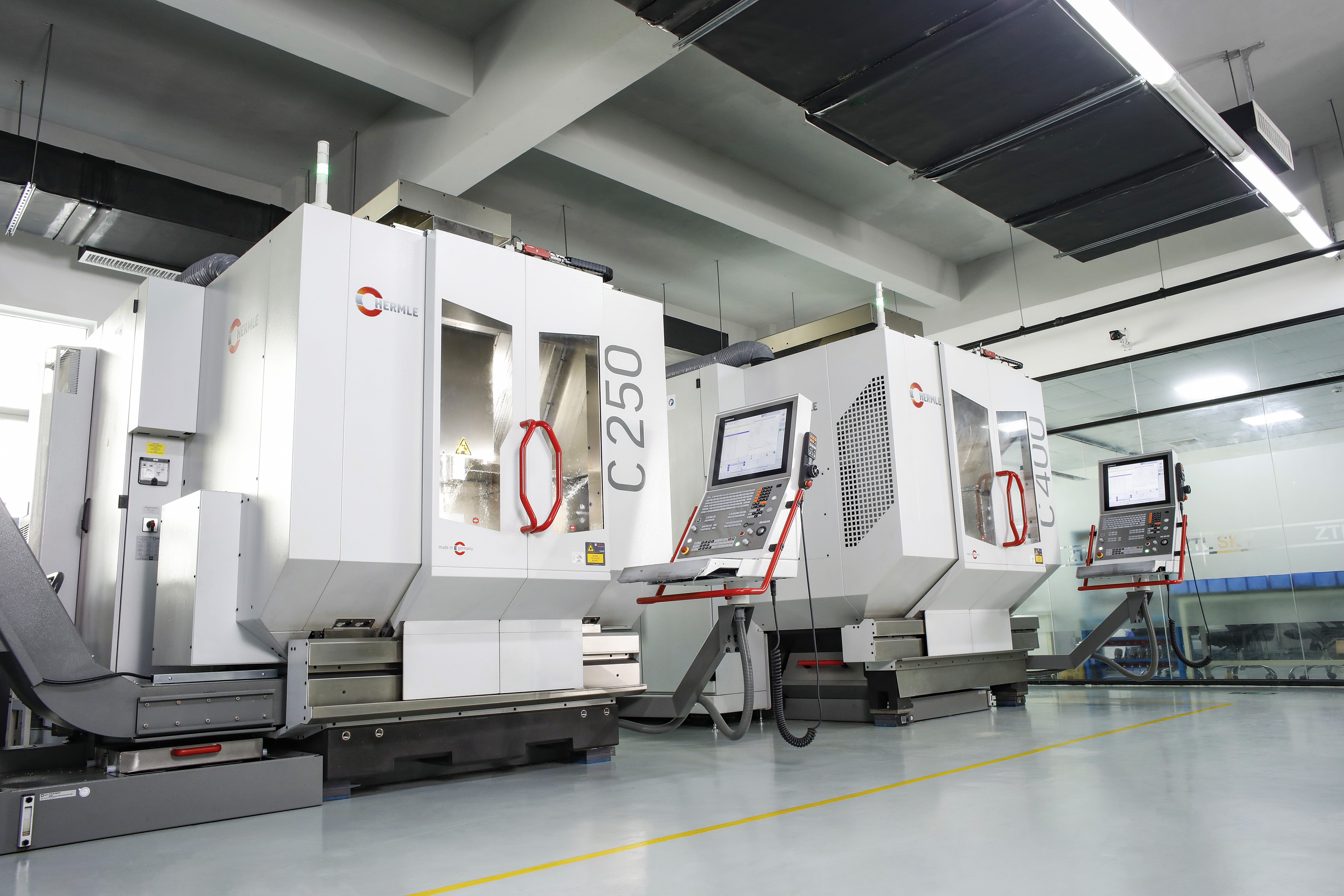
Choose by the job each process must perform.
Start with the finished part—not with a supplier’s favorite machine. Geometry, load path, critical surfaces, production quantity and acceptable evidence determine whether one primary process or a hybrid route is most defensible.
Strong candidate for integrated ribs, bosses, curved walls and internal passages created with cores or die features.
Strong candidate when deformation path, heat treatment and grain flow can support fatigue, impact or pressure duty.
Strong candidate for prototypes, low volume and tight, cutter-accessible features made from available certified stock.
Cast or forge the economical blank, then machine datums, bores, threads, sealing faces and controlled interfaces.
One part, three material histories
The first process changes more than shape.
A process name alone is not a material property. A cast component may come from sand casting, investment casting, permanent-mold casting or high-pressure die casting. A forging may be open-die, impression-die, rolled-ring, hot, warm or cold. A machined component may begin as rolled plate, extruded bar, forged billet or a heat-treated casting. Each variant brings a different capability window.
This distinction matters because buyers often compare incomplete scopes. A raw casting quote does not include the same work as a pressure-tested, machined and coated housing. A forged blank does not include the same evidence as a heat-treated, ultrasonically examined and finish-machined shaft. A machined prototype from plate does not automatically validate a later casting or forging, because the production material history will change.
What does “near-net shape” actually mean?
A near-net process creates a blank that already resembles the finished component, reducing later material removal. Casting and forging can both be near-net, but neither is automatically waste-free or ready to ship. Castings may carry gates, runners, risers and machining stock. Forgings may carry flash, scale, crop loss and allowance. The meaningful metric is the complete route’s accepted yield—not a generic claim that one process “uses less metal.”
Casting vs forging vs machining at a glance
The useful comparison is conditional—not absolute.
The table describes common starting tendencies. Supplier capability, alloy, geometry, section size, heat treatment, quantity and acceptance criteria can shift the result.
| Decision factor | Casting | Forging | Machining |
|---|---|---|---|
| Shape mechanism | Molten metal fills a mold and solidifies. | Solid stock is compressed and plastically deformed. | Cutting or abrasive tools remove selected material. |
| Typical geometry strength | Complex contours, ribs, bosses, part consolidation and cored internal passages. | Robust load-bearing contours that allow controlled flow, draft, radii and die release. | Precise cutter-accessible faces, bores, threads, pockets and freeform surfaces. |
| Bulk material condition | Created through filling, cooling and solidification; local structure depends on section and thermal history. | Influenced by starting stock, deformation path, reduction, temperature and heat treatment. | Inherited mainly from bar, plate, extrusion, casting or forging; cutting changes the near-surface condition. |
| Dimensional control | Ranges from broad sand-casting variation to closer investment and die-casting capability; critical features are often machined. | Ranges from open-die blanks to cold or precision forgings; critical interfaces are often machined. | Usually strongest for selected accessible final features, subject to stiffness, setup, thermal and measurement controls. |
| Tooling commitment | From simple patterns or printed molds to complex hardened dies, slides and core tooling. | From standard open tools to engineered preform, finish and trim dies. | CAM, fixtures, jaws, cutters, probes and gauges; usually easier to revise before automation is frozen. |
| Common risk family | Shrinkage, gas, inclusions, cold shuts, hot tears, core shift and distortion. | Laps, folds, underfill, mismatch, scale pits, decarburization and cracks. | Tool wear, chatter, deflection, burrs, datum error, distortion and surface damage. |
| Commercial starting point | Complex near-net shapes and repeated geometry; exact volume fit depends on casting method. | Critical structural blanks or efficient repeat shapes; open die also supports large low-volume parts. | Prototypes, low volume, design changes and precise secondary operations. |
Technical context: American Foundry Society, Forging Industry Association Product Design Guide, and NIST machining process planning.
 Process 01 · Casting
How casting works
Liquid metal reproduces a mold—then solidification controls the result.
Casting converts molten metal into a shaped solid. The mold defines external geometry; cores can create internal spaces. The foundry controls alloy chemistry, melt treatment, mold preparation, gating, filling, feeding, cooling, shakeout, cleaning, heat treatment and inspection.
Metal contracts as it cools. Thick regions remain hot longer than thin regions, so an inadequately fed hot spot may form shrinkage. Turbulent filling can entrain gas or oxide films. Core movement can shift an internal passage. Good design manages those mechanisms before inspection.
 Process 02 · Forging
How forging works
Compression changes shape and can redirect material flow.
Forging plastically deforms solid stock under compressive force. The starting material may be bar, billet, ingot or a preform. Depending on the alloy and shape, the operation may be hot, warm or cold, using open tools, impression dies, rolls or upsetters.
The advantage is conditional—not magical. A qualified route can refine the starting structure and orient macrostructural flow around a part. When the flow direction, heat treatment, surface and load path agree, fatigue, impact and toughness performance can benefit. Poor preforms can instead create laps, folds or unfavorable flow.
 Process 03 · Machining
How machining works
Cutting creates controlled features—but inherits the blank’s material history.
Machining removes material from bar, plate, billet, extrusion, casting or forging. Turning creates rotational features; milling produces faces, contours and pockets; drilling, boring and reaming control holes; grinding can finish hardened or precision surfaces.
CNC does not guarantee one universal tolerance. Capability depends on workpiece stiffness, tool reach, workholding, setup count, datum transfer, material behavior, machine condition, thermal stability, tool wear and measurement uncertainty. Machining also does not independently define bulk strength—the starting material and heat treatment do.
Seven differences that change the answer
Casting vs forging vs machining cannot be settled by one “best” label.
Each factor can change the route independently. A shape may favor casting while its load path favors forging and its critical interfaces still require machining.
Forging often gains an advantage for directional cyclic or impact duty, but only when alloy, cleanliness, reduction, flow direction, heat treatment, surface and load path are suitable. A sound casting or machined wrought part can still meet demanding requirements.
Casting is often best suited to integrated ribs, bosses and enclosed passages. Forging needs practical metal flow and die release. Machining needs cutter entry, collision clearance, a viable internal radius and chip evacuation.
Machining usually offers the closest control of selected accessible final features. Precision casting and cold or near-net forging can also create close geometry, while critical cast and forged surfaces are commonly finish-machined.
Hard dies can improve repeat output but make late revisions expensive. Machining usually launches faster from available stock, although complex fixtures, cutters, probes, CMM programs and automation are still real nonrecurring costs.
There is no universal break-even quantity. Sand casting and open-die forging may serve one-off work; die casting, cold forging and multi-cavity automation need repeat demand. Small automated machined parts can remain economical at scale.
Near-net geometry may reduce cutting, but casting still has gates, risers and yield loss; forging has crop, flash and scale; machining has chips, cutter wear and machine time. Compare actual route yield and scrap recovery.
Casting emphasizes filling and solidification risks; forging emphasizes flow, temperature and inherited-stock risks; machining emphasizes datum, cutting and distortion risks. Inspection must target credible failure modes and functional zones—not every method everywhere.
Which process is cheaper?
Price the accepted finished part—not the blank.
Machining can avoid hard tooling, casting can consolidate geometry and forging can reduce structural risk. None is universally cheapest because each quote can include a different boundary.
When casting can win
Complex geometry or internal passages remove extensive cutting, fabrication or assembly.
- Repeated geometry can amortize the chosen mold system
- Part consolidation removes joints and leak paths
- Near-net stock reduces purchased metal and cycle time
- Soundness and machining cleanup remain priced risks
When forging can win
Structural performance, material distribution and repeat reliability carry real life-cycle value.
- Directional loads justify engineered flow
- A preform can reduce finish stock removal
- Stable demand can amortize dies and trim tools
- Heat treatment, NDT and machining still belong in scope
When machining can win
Low tooling commitment and revision speed can outweigh higher stock removal.
- Prototypes, bridge quantities and spares
- Designs likely to change before maturity
- Compact shapes with accessible features
- Available certified stock and reasonable buy-to-fly ratio
How to choose the manufacturing process
Start with the requirement that cannot fail.
The first route to investigate should reflect the dominant geometry, load, quality or launch constraint. It is a starting point for DFM—not an automatic final answer.
Cast, then machine
Cores create the bulk flow path; machining controls datums, sealing faces, bores and threads.
Validate: soundness, core position, cleanup and leak performance.Forge, heat-treat, then machine
Controlled material flow can support fatigue and toughness when it follows the real load path.
Validate: flow, heat treatment, surface, NDT and test location.Machine from available stock
Avoid hard tooling while the design, datums and interfaces are still changing.
Validate: stock form, grain direction, distortion and cycle time.Evaluate die casting
Integrated details and fast repeat cycles may justify a hardened die and follow-up machining.
Validate: fill, venting, porosity zones, cavity variation and leak test.Open-die or rolled-ring forging
Progressive working can create a critical large blank without a complete impression die.
Validate: reduction, heat treatment, UT, test orientation and runout.Keep direct machining in the comparison
Automation and standard stock may remain competitive even when annual volume rises.
Validate: setup count, tool life, unattended capability and measurement.Why many parts use more than one process
The primary process creates the blank; the next process creates function.
Hybrid routes assign each operation the job it performs best. They also require shared datums, allowances and change control across suppliers.
Curved walls, ribs, bosses and internal passages.
Flanges, bores, threads, sealing lands and datums.
Core shift, machining stock, porosity-sensitive areas and leak test.
Near-net mass distribution and planned material flow.
Bearing seats, gear features, threads, faces and datums.
Avoid excess allowance that cuts through the intended contour.
Plate, bar, extrusion or billet with known condition.
CAM and workholding adapt while the product evolves.
Rolled plate, extruded bar and forged billet are not interchangeable labels.

Design the route as one system
Allowances, datums and quality zones must survive every operation.
A forged crankshaft may still need trimming, heat treatment, scale removal, straightening, NDT and extensive machining. A casting may need gate removal, heat treatment, pressure testing and machining. The primary process determines the blank; the finished drawing determines whether every later operation can create and verify function.
Resolve the parting line, draft, flash, cores, feeders, preform, grain-flow objective, machining allowance, datum transfer, fixture access and inspection coverage before hard tooling is released. Otherwise, the last supplier in the route inherits the first supplier’s assumptions.
- Mark surfaces that remain as-cast or as-forged.
- Identify surfaces that must clean up completely.
- Separate cosmetic regions from fatigue, pressure and sealing zones.
- Define who owns intermediate inspection and final acceptance.
Quality risks and inspection
Inspect the failure mechanism—not the process reputation.
No inspection method proves every property. The plan must state the stage, coverage, frequency, acceptance level, personnel qualification, records and nonconformance route.
Filling and solidification
Shrinkage, gas, entrainment, inclusions, cold shuts, hot tears, core shift and distortion depend on local geometry and process control.
- Use RT or CT selectively for credible volumetric risks
- Use PT or MT for suitable surface-breaking risks
- Add leak or pressure testing where function requires it
- Define quality zones instead of one vague porosity rule
Flow, temperature and stock
Laps, folds, underfill, mismatch, scale pits, decarburization, cracks and inherited indications require route-specific controls.
- Verify starting-stock traceability and forging schedule
- Use macroetch where flow orientation is critical
- State UT procedure and ordered quality level
- Place mechanical tests in meaningful locations
Datum, cutting and release
Tool wear, chatter, deflection, burrs, setup error, heat drift and residual-stress movement can appear only after cutting or unclamping.
- Control tools, offsets, programs and fixtures
- Inspect critical features after the final setup
- Match gauges and CMM strategy to functional datums
- Check edges, cleanliness and surface texture explicitly
RFQ and purchase-order checklist
Give suppliers the evidence needed to propose a complete route.
A good RFQ explains function and risk while controlling substitutions. It does not force every supplier to guess which surfaces, defects or documents matter.
Send with the RFQ
- Revision-controlled 3D model and 2D drawing
- Application, loads, cycles, pressure, temperature and environment
- Exact alloy, product specification, delivery condition and traceability
- Mandatory, preferred or permitted alternative manufacturing routes
- Prototype, batch, annual and lifetime volume with ramp timing
- Functional datums, CTQs, threads, fits, leak paths and critical zones
- As-cast/as-forged surfaces and surfaces requiring machining cleanup
- Heat treatment, hardness, tests, coating and cleanliness
- Repair welding, impregnation, blending and rework restrictions
- NDT method, stage, coverage, frequency, level and records
- FAI, PPAP, control plan, MTR, CoC and retention where applicable
- Tool ownership, life, maintenance, storage and transfer rights
Require the supplier to return
- The complete route, including subcontracted heat treatment, finishing and inspection
- DFM risks, drawing exceptions and every commercial assumption
- Parting line, draft, core strategy, forging flow, datum plan and setups as applicable
- Tooling/NRE, ownership, expected life, maintenance and lead time
- Prototype, launch and mature-volume unit prices with MOQ constraints
- Expected blank and finished weights, yield, secondary work and inspection burden
- Qualification plan tied to critical features and failure modes
- Capacity, ramp and written notification rules for any source or process change
From manufacturing route to laser process
Need to clean, join or permanently mark the finished metal part?
Send Oceanplayer the exact alloy, product form, geometry, surface condition and production target. We can review whether laser cleaning, welding or marking fits the manufactured part and identify the representative samples needed before equipment selection.
- Include these details
- Exact grade, alloy, temper or heat-treatment condition
- Cast, forged, wrought or machined product form
- Photos, drawing, dimensions and surface condition
- Cleaning, joining or marking objective
- Required appearance, integrity and acceptance evidence
- Parts or area per shift and automation target
Continue the manufacturing decision
Related material and fabrication resources
Frequently asked questions
Casting vs forging vs machining questions buyers ask
These answers give a screening direction. Final route approval still depends on the drawing, service load, alloy, process variant and supplier evidence.
What is the main difference between casting, forging and machining?
Casting shapes molten metal inside a mold, forging reshapes solid metal with compressive force, and machining removes material with cutting or abrasive tools. Casting is often selected for complex near-net geometry, forging for engineered material flow and demanding loads, and machining for precise accessible features and design flexibility.
Is forging always stronger than casting or machining?
No. Forging can provide favorable fatigue, impact and toughness performance when the alloy, stock quality, deformation path, grain flow, heat treatment, surface and load direction are appropriate. A sound casting or machined wrought part can also satisfy demanding structural requirements. Machining itself does not define bulk strength independently of the starting stock.
Which process is cheapest?
There is no universal winner. Machining often avoids major hard tooling at low volume. Casting or closed-die forging can reduce serial cost when stable volume amortizes tooling and near-net geometry reduces downstream work. Compare the accepted finished-part cost, including tooling, material, heat treatment, machining, inspection, scrap, logistics and risk.
Which process provides the tightest tolerances?
CNC machining generally offers the closest control of selected cutter-accessible final features. Precision casting and cold or near-net forging can also create close geometry, but capability depends on method, alloy, feature size, datum structure, equipment and supplier. Critical cast and forged features are often finish-machined.
Are cast parts always weak or porous?
No. Casting performance depends on alloy, process, section thickness, mold filling, solidification, heat treatment, surface condition, discontinuity acceptance and service load. A properly designed and controlled casting can meet pressure, wear, temperature and structural requirements. The inspection plan should focus on functional quality zones rather than assume every casting has the same risk.
Do forged parts still need CNC machining?
Often yes. Forging creates the load-bearing blank and desired material distribution, while machining controls bores, bearing seats, threads, sealing faces, gear features and datums. Precision forging can reduce the amount of cutting, but the required final interfaces determine whether secondary machining is needed.
Can a cast part be CNC machined?
Yes. Cast-then-machine is a common production route. The casting creates bulk geometry and internal passages; machining creates critical interfaces. Casting datums, machining allowance, core shift, porosity-sensitive zones, fixture access and leak requirements should be reviewed before tooling is released.
Is machining from billet better than casting?
It can offer faster design changes, tight accessible features and lower initial tooling, but it may require more purchased material and machine time. Casting may be better for complex geometry, internal passages, part consolidation or sustained volume. The answer depends on function, quality, quantity, schedule and total cost.
Which process is best for metal prototypes?
Machining from available certified stock is often the fastest practical route because it avoids production molds or dies. Large parts or casting-specific geometry may favor sand casting, printed molds or investment-casting prototypes. A machined prototype does not automatically validate the material history or quality risks of a future casting or forging.
What information does a supplier need to recommend a process?
Provide the CAD model and drawing, exact material and condition, service loads, critical dimensions and surfaces, heat treatment, quality and traceability requirements, prototype and annual quantities, program life, delivery timing and permitted alternative routes. Ask for a documented DFM and total-cost comparison rather than a process label alone.
Technical references
Sources behind the manufacturing comparison
The page uses standards and institutional sources to define process mechanisms and purchasing boundaries; supplier-specific capability still requires direct validation.
- American Foundry Society — About Metalcasting: definition and overall casting process.
- NIST — Solidification: flow, segregation, inclusions and porosity research context.
- MIT OpenCourseWare — Metal Casting: modern manufacturing-process instruction.
- Forging Industry Association — Product Design Guide: forging definitions, process variants, flow and design constraints.
- NASA-STD-6016: controls for critical metallic materials, forgings and process changes.
- NISTIR 5628 — Precision in Machining: machining accuracy and measurement context.
- ISO 8062-3:2023: general dimensional and geometrical tolerances and machining allowances for castings.
- ASME Y14.5: dimensioning and tolerancing language for product definition.
- ASTM A388/A388M: ultrasonic examination of steel forgings and ordered quality levels.
- ASTM E446: reference radiographs for steel casting discontinuities.