

Metal Reflectivity at Fiber Laser Wavelengths Copper, Aluminum & Gold
Copper, aluminum and gold are not impossible to process with a fiber laser. They are harder because a cold, smooth surface can return most near-infrared light before stable coupling begins, while thermal conductivity, oxide, roughness, geometry and phase change keep moving the process window.
 Copper / Cu
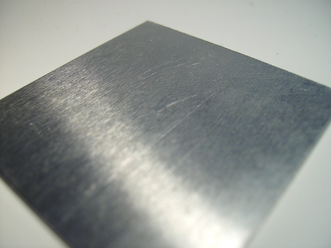 Aluminum / Al
 Gold / Au
A smooth metallic surface can return most incident near-infrared energy before heating or melting changes the optical state.
Temperature, phase, oxide, roughness, angle, polarization, plume and keyhole geometry all change effective absorption.
Source protection, beam profile, focus, pulse control, travel strategy and monitoring must create a repeatable coupling window.
Validate alloy, finish, coating, thickness, joint, tolerance and lot variation - not only a polished showcase coupon.
What does metal reflectivity mean at a fiber-laser wavelength?
Reflectivity is the fraction of incident optical power returned by a surface. Absorptivity is the fraction converted into energy inside the material. Transmissivity is the fraction that passes through. For a sufficiently thick, opaque metal, transmission is negligible, so the first-pass optical balance is often simplified to absorptivity being approximately one minus reflectivity.
That relationship is useful, but it is not a complete process model. A value measured on a cold, flat, polished coupon at normal incidence does not describe a hot weld pool, a roughened mark, a powder bed, a plated stack, a curved part or a keyhole. In real laser processing, the surface and beam interaction evolve together.
Why highly conductive metals create a second difficulty
Low initial absorption is only the first obstacle. Copper, aluminum and gold also move heat rapidly away from the interaction zone. NIST reference data near room temperature list thermal conductivity around 400 W/mK for copper, 317 W/mK for gold and 235 W/mK for aluminum, compared with about 15 W/mK for 304 stainless steel. The exact value depends on grade, temper and temperature, but the comparison explains why a process can need high local intensity even when average heat input is already substantial.
They reinforce the difficulty, but they are not the same property. A successful recipe must cross the optical coupling threshold and manage the rate at which heat leaves the interaction zone.
Convert reflectance into first-pass absorptance
Use the presets to understand scale, or enter a measured reflectance for your wavelength and surface. The output deliberately stays separate from process efficiency.
Set the optical condition
Preset values use the Rakić Lorentz-Drude optical model at 1064 nm for an idealized cold, smooth, opaque surface.
At 1,000 W incident power, the simplified balance corresponds to 22 W absorbed at the boundary condition.
Do not use this watt figure as a melt, cut or weld prediction. Temperature-dependent optical constants, multiple reflections, plume, keyhole geometry, beam distribution and heat flow can change effective coupling dramatically.
Modeled reflectance near 1064 nm
These values provide a consistent comparison of cold, smooth, opaque elemental surfaces. They should not be copied into a production cycle-time calculation.
| Material and condition | Reported reflectance or absorptance | What the comparison demonstrates |
|---|---|---|
| Idealized copper optical model, 1064 nm | Approx. 97.8% reflectance / 2.2% absorptance | A useful smooth elemental baseline, but not a manufacturing-surface guarantee. |
| As-received commercially pure copper, 1053 nm | Approx. 94% reflectance / 6% absorptance in the cited engineering-surface study | A real surface can absorb materially more than an ideal optical-constant calculation. |
| Polished vs laser-structured copper, 1070 nm | Absorptivity increased from about 4% to 11.3% in the cited structuring study | Deliberate surface topography can change coupling and weld stability without changing the bulk element. |
| Idealized aluminum optical model, 1064 nm | Approx. 94.9% reflectance / 5.1% absorptance | The ideal pure-metal baseline is substantially more reflective than many practical surfaces. |
| As-received pure aluminum and selected 5xxx/6xxx alloys, 1053 nm | About 84% reflectance for pure aluminum and about 76% for AA5251/AA6082 in the cited study | Alloy, oxide and engineering finish can dominate the gap between handbook optics and shop-floor coupling. |
| Gold production surfaces | No single production value is used here | Bulk gold, jewelry finish, bond pad and thin plating require separate measurements or trials. |
The engineering-surface values above are representative measurements under defined study conditions, not universal limits. They are included to show why wavelength and surface state must accompany every percentage.
| Material | Near-IR starting challenge | What changes coupling | Primary process concern | Useful comparison route |
|---|---|---|---|---|
| Copper | Very high cold-surface reflectance plus very high thermal conductivity. | Oxide, roughness, temperature, melt formation, keyhole and multiple reflections. | Unstable start, spatter, porosity and reflected energy returning toward the optics. | Compare protected near-IR with green or blue where start stability and low spatter dominate. |
| Aluminum | High reflectance, high conductivity and a persistent native oxide whose behavior differs from the substrate. | Alloy, oxide thickness, finish, contamination, casting condition, melt pool and geometry. | Porosity, oxide inclusion, hot cracking, inconsistent marking and transition sensitivity. | Near-IR is a mature baseline; evaluate visible sources or pulse control when the cold start remains limiting. |
| Gold | Very high near-IR reflectance on a clean metallic surface. | Surface finish, thin-film thickness, substrate, temperature, roughness and pulse regime. | Insufficient coupling on bulk material or excessive penetration through thin plating. | Compare near-IR, green and short-pulse routes against a strict material-loss limit. |
A published number is only meaningful when wavelength, incidence, polarization, surface preparation, temperature, phase and measurement method are known.
Reflectivity is not constant during laser processing
The process can move through several optical states in milliseconds. A recipe must manage the transitions, not merely the final steady state.
Specular return can dominate
Polish, wavelength, angle and polarization set the starting reflection. Oil, oxide and texture can alter the value in either a helpful or harmful way.
Optical constants begin to change
Electron and lattice behavior changes with temperature. The absorbed fraction can rise or fall depending on material and condition.
The surface stops behaving like the coupon
Ripples, melt motion, oxide disruption and changing angle scatter light and create additional paths for absorption.
Multiple reflections can trap energy
A cavity or powder layer lets the beam interact repeatedly. Effective coupling can become much greater than one flat-surface measurement suggests.
Why two credible reflectivity values may disagree
Different values do not automatically mean one source is wrong. They may describe different optical and physical conditions.
Wavelength and bandwidth
Reflectance is spectral. A value at 450 nm, 515 nm, 1064 nm or 10.6 µm cannot be substituted without a material-specific spectrum.
Alloy and purity
Elemental copper data does not fully predict Cu-ETP, OFHC copper, aluminum alloys, gold plating or a mixed substrate stack.
Finish and roughness
Polished, rolled, brushed, machined, blasted and laser-structured surfaces redistribute reflected light differently.
Oxide and contamination
Native oxide, intentional oxide, fingerprints, lubricant and coating add their own absorption and thermal behavior.
Temperature and phase
Cold solid, hot solid, liquid metal and vapor-cavity conditions can have different reflectance and effective energy coupling.
Geometry and measurement
Normal versus oblique incidence, polarization, integrating sphere method, detector geometry and surface curvature affect the reported result.
Three materials, three different process stories
Copper, aluminum and gold share high near-infrared reflectivity, but a supplier should not use one generic "reflective metal" recipe. Each material brings a different combination of heat flow, oxide, alloy behavior, thickness and acceptance risk.

Low initial coupling can become a fast thermal transition
Clean copper can reflect nearly all incident 1 µm light at room temperature, while its high thermal conductivity removes heat from the spot. This makes process initiation sensitive. Once the surface heats, roughens or melts, coupling may rise quickly, so a recipe that only adds power can jump from insufficient interaction to spatter, expulsion or keyhole instability.
Published copper results illustrate why surface state matters. Direct microcalorimetry has reported about 2.8% absorptance for a clean flat copper surface at 1070 nm. Separate work on tailored copper surfaces reported approximately 4% for a polished state and 11.3% after structuring. Temperature-dependent Cu-ETP measurements also show that polished, rolled, oxide-reduced and molten states should not be treated as interchangeable.
The oxide and alloy can matter as much as the base metal
Aluminum combines high near-infrared reflectance, high thermal conductivity and a persistent native oxide. The oxide has a much higher melting temperature than the aluminum beneath it, and contamination or trapped gas can contribute to porosity. Different alloy series also respond differently to solidification cracking, vaporization of alloying elements and heat treatment.
Near-infrared fiber lasers remain widely used for aluminum cutting, welding and marking because of mature high-power sources and beam delivery. The engineering task is to qualify the actual alloy and condition: bare, anodized, painted, cast, rolled, brushed or coated. A result obtained on clean 6061 sheet does not automatically transfer to a die casting, 5xxx alloy or anodized enclosure.
Bulk gold and thin gold plating are different applications
Gold has very high room-temperature reflectance near common ytterbium fiber-laser wavelengths. Bulk gold may therefore need carefully concentrated intensity or a more strongly absorbed wavelength to initiate a stable interaction. Thin gold plating creates the opposite concern: the process may remove the coating or expose the substrate before a visually acceptable mark is formed.
The correct acceptance criterion depends on the product. Jewelry may prioritize appearance and edge quality; electronics may prioritize contact resistance, bond integrity and zero substrate damage; a traceability mark may need contrast without unacceptable depth. Pulse duration, spot size and wavelength should be evaluated against the total coating stack rather than the word "gold."
Welding, marking, cutting and additive manufacturing
Reflectivity is an input to the process window, not the only decision. The required interaction time, depth, heat flow and quality evidence change with the application.
Laser welding
Welding must initiate a melt pool, transition into stable penetration and preserve that state through starts, stops, corners and fit-up variation.
- Manage the cold-start threshold separately from steady travel.
- Control keyhole stability, spatter, porosity and back reflection.
- Validate penetration, strength or electrical resistance across lots.
Laser marking and engraving
A mark may rely on oxidation, color change, roughening, ablation or material removal. High reflectance can reduce initial contrast or require excessive fluence.
- Use pulse energy, duration, frequency and hatch as a coordinated set.
- Separate bare, anodized, painted and plated surfaces.
- Measure readability, depth and substrate damage.
Laser cutting
Cutting adds piercing, assist gas, kerf geometry, molten-metal ejection and optics exposure. A stable cut can still fail at the pierce or on reflective returns.
- Qualify pierce time and reliability independently.
- Inspect taper, dross, roughness, heat-affected zone and edge geometry.
- Monitor protective-window condition and reflected-light events.
Powder-bed and directed energy processes
Powder changes the optical geometry. Multiple scattering between particles can increase effective absorption compared with a flat dense surface.
- Do not apply bulk polished reflectivity directly to powder.
- Control particle size, packing, oxide, layer condition and reuse.
- Validate density, defects, chemistry and repeatability.
Can back reflection damage a fiber laser?
Returned energy can create alarms, source derating, instability or damage if it reaches sensitive parts of the optical chain. Risk depends on the source architecture, isolators, delivery fiber, processing head, angle, beam path, workpiece geometry and power level. A material being "reflective" does not by itself prove that damage will occur, but it is a reason to verify the complete system rating and warranty conditions.
Do not rely on tilting the part as the only protection. An angle can steer a specular return away from the source, but it also changes focus, spot shape, joint access and enclosure geometry. Any deliberate angle strategy should be approved by the machine supplier and tested under worst-case part tolerance.
Rated material capability
Confirm the laser source is specified for the intended reflective material, power and process, including start-up and fault states.
Protected beam delivery
Review isolators, delivery fiber, head design, protective windows, nozzle condition and maintenance limits.
Controlled return path
Validate head angle, scan direction, part curvature, fixture orientation and focus tolerance without compromising safety.
Alarm and monitoring history
During trials, record reflected-light alarms, shutdowns, derating, window contamination and any maintenance triggered.
Which source family should you compare first?
This selector does not produce a laser recipe. It organizes the first supplier trial around material, process and purchasing priority.
Describe the application
Choose the closest condition. The comparison route updates instantly.
Compare protected near-IR with green or blue
For copper welding where start stability is the priority, benchmark a mature back-reflection-protected near-IR process against a visible-wavelength route with stronger cold-surface coupling.
- Primary risk: rapid transition from weak coupling to unstable melting
- Trial evidence: starts, penetration, spatter, porosity, reflected-light alarms and repeatability
- Decision rule: select by accepted-part throughput and lifecycle cost, not absorption alone.
Control energy density, timing and geometry - not blind wattage
More average power can help cross an interaction threshold, but it can also magnify the transition into overheating. These levers should be tuned as a coordinated system.
Make the real input repeatable
Remove inconsistent oil, fingerprints and debris. Document oxide, roughness, coating and normal supplier variation instead of hiding them with a specially prepared coupon.
Separate initiation from steady travel
Use a controlled pulse, power ramp, pierce routine, preheat or lead-in path where the application permits. The start may need a different intensity than steady processing.
Set intensity with margin
Coordinate power, spot size, focus position, peak power, duty cycle and motion so the interaction threshold is crossed without uncontrolled overshoot.
Shape space and time
MOPA pulse control, multiple passes, hatch strategy, wobble, ring modes, dual beams and shaped profiles can widen a window when matched to the acceptance goal.
Control gas, plume and heat flow
Shielding or assist gas, extraction, nozzle condition, clamping, heat sinking and joint-gap consistency influence both optical coupling and final quality.
Detect loss of coupling early
Vision, reflected-light signals, plume or thermal sensing, OCT, acoustic data and downstream inspection can reveal drift before defective parts accumulate.
When another wavelength may be worth the comparison
Shorter wavelengths can improve initial coupling for selected reflective metals, especially copper. They are not automatically the best economic choice for every part.
| Source family | Typical industrial band | Potential advantage | Tradeoff to validate | Good comparison question |
|---|---|---|---|---|
| Near-infrared fiber or disk | Approx. 1030-1080 nm | Mature high-power platforms, efficient delivery, broad integration base and established processing heads. | Low cold-surface coupling on copper and gold; strong back-reflection engineering may be required. | Can pulse control, beam shaping or a dual-beam profile create a stable window at the required speed? |
| Green | Approx. 515-532 nm | Substantially higher cold copper absorption in published comparisons; can improve start stability and reduce spatter. | Available power, efficiency, source cost, service ecosystem and total throughput may differ from near-IR. | Does the wider window reduce scrap and inspection enough to justify system cost? |
| Blue | Approx. 450 nm | Strong copper absorption and a potentially stable conduction-mode route for selected joining and deposition tasks. | Beam quality, focus, power density, system architecture and integration must match the actual process. | Can blue meet penetration and speed, or is a hybrid/combined source more effective? |
| UV or ultrashort-pulse | Application dependent | Fine features and low average thermal loading for precision marking or micromachining. | Throughput, cost, pulse-energy limit and depth capability may not fit bulk processing. | Is the real objective a precision surface modification rather than bulk melting? |
Near-infrared fiber lasers often overcome low initial coupling with high brightness, controlled peak power, beam shaping and mature protection. Green or blue sources can improve cold coupling. The better system is the one that repeatedly meets acceptance criteria at the required throughput and lifecycle cost.
A five-stage validation workflow
A supplier trial should be a capability study, not one attractive sample. It must reveal the process window and failure modes across representative variation.
Define the real material
Record alloy, temper, thickness, coating or plating stack, oxide, roughness, cleanliness, supplier and lot variation.
Set acceptance evidence
Define penetration, strength, resistance, edge quality, mark contrast, depth, code grade, distortion or surface-damage limits.
Compare source routes
Hold the acceptance target constant while comparing wavelength, beam mode, pulse strategy, spot, focus, gas and travel method.
Run a repeatability study
Include starts, stops, corners, gaps, part-height tolerance, consecutive parts, heat accumulation and protective-window contamination.
Lock the process window
Document nominal and high/low limits, monitoring thresholds, failure examples, maintenance triggers and revalidation ownership.
Reflective-metal sample-test checklist
Representative lots
Use production material and at least two representative lots or surface conditions. Do not silently substitute a polished laboratory coupon.
Complete recipe record
Record source, wavelength, power, spot size, focus, beam profile, pulse settings, gas, fixture angle, motion and monitoring configuration.
Consecutive-part evidence
Run enough parts to expose start-up drift, heat accumulation, window contamination, nozzle changes and true cycle repeatability.
Geometry extremes
Inspect starts, stops, corners, edges, curves, joint gaps, thin sections and the extremes of part-height tolerance.
Application-specific inspection
For welds inspect penetration, porosity and strength; for cuts inspect taper and dross; for marks inspect contrast, depth, readability and durability.
Process-window limits
Request high and low parameter limits plus failure examples. One nominal recipe does not prove manufacturing robustness.
Reflected-light history
Review alarms, source derating, shutdown events, protective-window condition and maintenance caused by the trial.
Change-control ownership
Agree who owns recipe access, acceptance limits, material-change review, revalidation and technical support.
Common mistakes when using metal reflectivity data
Publishing one percentage without wavelength, surface, temperature, incidence and measurement method.
Treating reflectivity and thermal conductivity as the same problem or combining them into one vague explanation.
Assuming the absorbed fraction remains constant after the surface heats, roughens, melts or forms a keyhole.
Selecting by average wattage while ignoring peak power, pulse duration, spot, profile, focus tolerance and start control.
Using polished pure-metal data to predict a real alloy, casting, plated stack, anodized part or powder layer.
Treating bare, anodized and painted aluminum as one marking or cleaning application.
Applying bulk-gold parameters to thin gold plating without a material-loss or substrate-exposure limit.
Approving one good sample instead of validating a repeatable window across normal material variation.
Metal reflectivity and fiber lasers
The short answers below are planning guidance. Final settings require the actual alloy, surface, geometry and acceptance criteria.
Why does copper reflect fiber-laser light?
Copper's free-electron optical response produces very high reflectance in the near-infrared, including common ytterbium fiber-laser wavelengths around 1 µm. A cold smooth copper surface therefore absorbs only a small first-pass fraction, while high thermal conductivity rapidly distributes the absorbed heat.
Can a fiber laser mark, cut or weld copper?
Yes. Fiber lasers are widely used on copper, but the source and processing head must be suitable for reflective materials, and the recipe must control process initiation, intensity, focus, beam distribution, motion and reflected energy. A sample test should prove repeatability and optics protection.
Why is aluminum difficult for a fiber laser?
Aluminum combines high near-infrared reflectance with high thermal conductivity. Its native oxide, alloy chemistry, contamination and solidification behavior add further variability. Near-infrared fiber lasers can process aluminum effectively, but the actual alloy and surface condition must be qualified.
Does increasing laser power solve high reflectivity?
Not by itself. More power can help cross the coupling threshold, but once absorption rises it can also cause a rapid jump into spatter, excessive penetration or heat damage. Spot size, peak power, pulse duration, ramping, beam profile, focus, gas, motion and monitoring must be tuned together.
Can back reflection damage a fiber laser?
Returned energy can cause alarms, instability, derating or damage if the complete source and optical chain are not designed for it. Confirm the laser source, fiber, head, protective optics, geometry and warranty are rated for the material and process rather than assuming any fiber laser is suitable.
Are green or blue lasers always better for copper?
No. Green and blue wavelengths can provide much stronger cold-surface coupling to copper, which may improve stability and reduce defects. Near-infrared systems may still provide better power, speed, integration maturity or lifecycle cost. Compare accepted-part throughput and process capability, not absorption alone.
Does oxidation improve laser absorption?
An oxide or dark surface can increase absorption in some conditions, but oxide thickness and uniformity may vary, and the oxide may be unacceptable in the final product. It should be treated as a controlled material condition, not an informal shortcut.
Can a fiber laser engrave gold or gold plating?
Yes, but bulk gold and thin plating require different strategies. Thin plating needs a strict depth and substrate-exposure limit. Validate pulse energy, wavelength, spot size, number of passes, contrast and durability on the complete plated stack.
Technical references and further reading
- Rakić, A. D. et al. "Optical properties of metallic films for vertical-cavity optoelectronic devices." Applied Optics 37(22), 5271-5283 (1998). Optica Publishing Group.
- NIST Center for Neutron Research. Reference tables for material properties, including room-temperature thermal conductivity. NIST reference tables.
- Hess, A. et al. Comparison of copper processing at 1070 nm and 515 nm. Fraunhofer publication record.
- Fraunhofer IWS. Green laser processing of highly reflective metals including copper, aluminum and gold. Fraunhofer IWS.
- Mattern, M. et al. Temperature-dependent reflectance of Cu-ETP at 1064 nm. Open-access full text.
- Gargalis, L. et al. Direct measurement of laser absorptivity in metal processing conditions, including flat and powder copper. Journal record.
- Tailored absorptivity of copper surfaces by laser structuring. Fraunhofer publication record.
- Bergström, D., Powell, J. and Kaplan, A. F. H. "The absorptance of steels to Nd:YLF and Nd:YAG laser light at room temperature." The associated engineering-surface dataset includes copper and aluminum comparisons near 1 µm. Open full text.
- NIST study of dynamic laser energy absorption during keyhole-mode processing. NIST publication PDF.
- IPG Photonics. Fiber laser fundamentals and industrial source architecture. Fiber Lasers 101.
- TRUMPF. Green wavelength laser technology for copper processing. Green light for welding copper.
Validate your material before choosing the laser system
Send Oceanplayer the alloy, surface, coating stack, thickness, process goal, production rate and acceptance criteria. We can organize a representative sample test around coupling stability, quality, reflected-light protection and repeatability.