

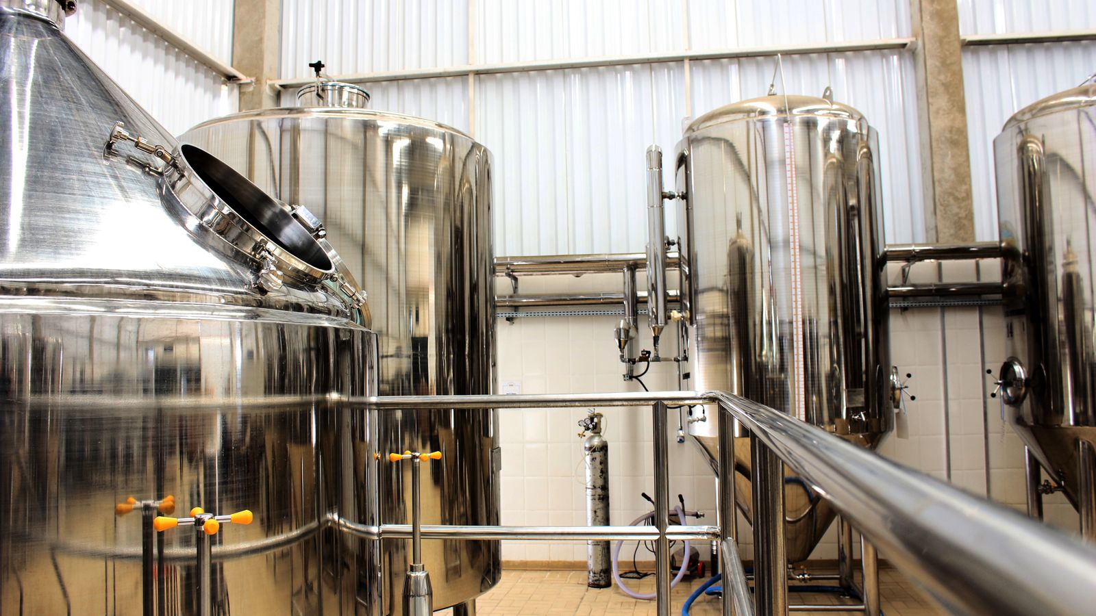
Can Handheld Laser Welding Produce Leak-Tight Stainless Steel Tanks?
Yes—but the answer comes from a controlled joint, a qualified process, and a service-matched leak test. A smooth weld bead alone does not prove liquid-tight, gas-tight, hygienic, vacuum, or pressure-boundary performance.
Known grade, controlled gap, stable fixture and a clear final test.
Incomplete fusion, porosity, starts/stops and hidden lap paths matter.
Macrosections show the weld; the production test checks the boundary.
Use the applicable code, qualification and safety framework.
Handheld laser welding can make a leak-tight stainless steel tank when the weld forms a continuous fused path, the joint stays within a controlled fit-up range, and the completed tank passes a test designed for its real service. This is realistic for many vented reservoirs, cooling-water tanks, jackets and low-pressure stainless assemblies.
The answer changes when the tank contains gas, operates under vacuum, cycles in pressure, handles a hazardous or corrosive medium, contacts food or pharmaceutical product, or falls under a pressure-vessel code. In those cases, “no visible leak” is only one acceptance condition. Strength, fatigue, corrosion, cleanability, procedure qualification, personnel qualification, examination and traceable records may also be required.
Can the laser melt the stainless steel? Can the weld create a continuous seal? Can the finished tank meet its leak, pressure, corrosion, cleanability and documentation requirements? A successful demonstration answers only the first question unless the other two are tested.
Define “leak-tight” first. A vented water tank, nitrogen enclosure and vacuum chamber do not need the same proof.
Design the seal path. The root, overlap and start-stop tie-in must close the intended boundary continuously.
Control the process window. Grade, thickness, fit-up, cleaning, focus, motion, shielding and filler cannot be treated as separate guesses.
Prove the weld and the tank. Representative sections show fusion; final leak testing checks the complete assembly.
Escalate high-consequence work. Pressure, vacuum, hazardous media and regulated service need the applicable engineering and qualification route.
What Does “Leak-Tight” Mean for a Stainless Steel Tank?
Convert the word into measurable conditions before choosing a machine, joint or test: medium, pressure or vacuum, temperature, stabilization and hold time, allowable leakage, test sensitivity, and what happens after a failure.
No visible liquid escapes during a defined fill or hydrostatic condition. A pinhole or weak tie-in may still be invisible before testing.
Evidence: defined liquid test and traceable result.Gas loss stays within a written acceptance limit during a controlled test window. Gas may reveal paths that temporarily retain water.
Evidence: bubble, pressure-change or other specified gas test.Hermetic is useful only when the allowable leak rate and test method are stated. The adjective alone is not a production criterion.
Evidence: calibrated tracer-gas or mass-spectrometer method where required.The tank must also satisfy its design basis, material, strength, fatigue, welding, examination, testing and documentation requirements.
Evidence: the governing code or specification plus required tests.Is Your Tank a Good Handheld Laser-Welding Candidate?
Describe the application to see the next engineering gate. This planner does not generate welding parameters or a pressure-test procedure.
The starting selection is a plausible pilot, but visual appearance alone cannot support a leak-tight claim.
- Write the medium and test acceptance conditions.
- Weld the actual grade, thickness and representative joint.
- Verify the root and perform a final service-matched leak test.
Planning support only. A competent engineer, the governing specification and qualified laser-safety personnel must control the actual welding and test plan.
Why Can a Handheld Laser Weld Seal a Tank—and Still Fail in Production?
Laser welding is a fusion process. Concentrated optical energy melts metal along the joint, and the moving molten pool solidifies behind the beam. If fusion is continuous across the intended seal path and the metal solidifies without a through-defect, the seam can retain liquid or gas.
The concentrated energy can also limit the width of the heated zone and reduce overall distortion in suitable thin-sheet work. That is useful on tanks, because distortion can open gaps, move the seam away from the focal reference, or make later closure difficult. It is still only a process advantage—not proof of penetration or leakage performance.
A handheld head makes short seams, complex access, repairs and high-mix production easier to approach. It also lets stand-off, head angle, travel, aim and overlap change with the operator. A reliable tank process reduces improvisation: the fixture locates the seam, the approved work instruction limits variables, and coupon plus assembly tests show whether the result is repeatable.
Which Tank Joint Designs Are Easiest to Seal and Inspect?
A surface bead can look closed while an unwelded root or interface remains open. Use representative geometry: flat scrap does not reproduce every curved shell, dished head, nozzle, corner or circumferential closure.
A continuous, verified root often gives the clearest pressure-boundary path. Tight alignment, stable focus and representative cross-sections are critical.
Escalate if required penetration or access cannot be verified.The overlap can hide an open path and create a crevice. A wider top bead does not prove that the internal interface is continuously sealed.
Weak choice where cleanability or crevice corrosion matters.Angle, fit-up and tie-in change around fittings. Inspect the full circumference, and separate a sealing weld from a structural load path when the design requires it.
Pressure-loaded nozzles need their governing design route.Gap, roundness, gravity and access can change through 360 degrees. The start-stop overlap is a common local leak point.
Test the entire circumference, not a convenient segment.Which Variables Control Leak-Tight Laser Welding?
Open each control to see why it changes both the weld and the evidence plan. A change in material, optics, head, fixture, gas, wire or technique can move the process outside the demonstrated window.
Material, grade, thickness and service
304L and 316L are common tank materials because they can be welded and offer useful corrosion performance in suitable environments. They are not interchangeable with duplex, ferritic, martensitic or highly alloyed stainless grades. Nor does a procedure on thin 304L prove a thicker 316L, duplex chemical tank or polished sanitary assembly.
Start from the material certificate, product form, thickness range, surface finish and actual medium. Grade selection must consider chlorides, temperature, cleaning chemistry, weld metal, heat tint and finished surface—not only the base-metal label.
Gap, mismatch, roundness and fixture
Autogenous laser welding is sensitive to a gap that changes along the seam. The top can remain attractive while one edge or the root loses fusion. Wobble broadens the molten zone and filler can add metal, but neither gives permission to ignore edge preparation.
The procedure should state allowed gap, mismatch, tack condition, clamping and correction route. Circumferential seams also need control of rolling tolerance, out-of-roundness, tack distortion, part weight and the way the operator or positioner reaches the full seam.
Cleanliness and contamination
Oil, cutting fluid, adhesive, marker ink, moisture, oxide and debris can disturb shielding or introduce gas into the molten pool. Clean both sides of the seal area using a method compatible with the material and service. The acceptable pre-weld condition should be visible in the work instruction, not left to personal judgment.
If a tank has previously contained flammable, toxic or unknown material, normal pre-weld wiping is not enough. Isolation, cleaning, atmospheric testing and hot-work authorization require a formal competent process.
Focus, travel, wobble, aim and filler wire
Power, beam profile, spot size, focal reference, wobble, travel, head angle and wire feed act together. The right control is an approved range that has produced acceptable samples—not one screenshot of settings. A setup that penetrates a tightly clamped flat coupon may underfill, burn through or lose root fusion on a curved shell with a variable gap.
Wire can add bead volume or help within a limited fit-up range. Its grade, feed position, angle and rate become procedure variables. Do not add wire only because a joint is poorly prepared.
Face shielding, root shielding and post-weld treatment
Shielding protects molten and hot metal from air. For a tank, the root may contact the product or corrosive medium, so its condition can matter as much as the face. Poor root shielding can leave heat tint and rough oxidation even if the seam holds water briefly.
Heat tint is not merely a color issue: oxide and a chromium-depleted region can lower local corrosion resistance. Cleaning, pickling and passivation are different operations. Post-weld treatment may restore a suitable surface, but it cannot turn incomplete fusion into a sound weld.
Starts, stops, tacks, transitions and repairs
Manual seams often fail at transitions. A start crater, missed overlap, poorly remelted tack or changed angle beside a fitting can create a local path. The welding procedure specification (WPS) or work instruction should define start-stop overlap, termination, tacks, corners and the point at which the operator must stop and escalate.
A repair is another controlled weld. Identify the defect, remove or prepare it as required, restore cleanliness and access, use an approved repair route, then repeat the relevant inspection and leak test. A cosmetic cover pass can hide the evidence without removing the cause.
What Evidence Proves a Stainless Tank Weld Is Leak-Tight?
Every level answers a different question. Skipping directly from visual appearance to production release leaves hidden failure modes unchecked.
What Visual and Dimensional Inspection Can Prove
Visual inspection can find accessible surface cracks, undercut, overlap, discoloration and profile problems. Dimensional checks can confirm alignment and the accessible root. Neither one proves the full internal weld or a specified leak rate.
Finds accessible surface shape, undercut, obvious cracks, overlap and discoloration. It does not prove the root or a leak rate.
Checks alignment, profile and the accessible inside surface. A borescope may help where direct access is limited.
A sectioned coupon can show fusion and penetration at the sampled location. It cannot prove every centimetre of a tank seam.
Penetrant finds surface-breaking discontinuities; radiography or ultrasonics can find selected internal imperfections. Method capability matters.
The completed boundary is tested with a method and sensitivity matched to the defined service—not a generic shop ritual.
Add mechanical, fatigue, corrosion, cleanability, code, customer and traceability evidence wherever the consequence requires it.
What Can Representative Macrosections and NDT Prove?
A macrosection is a polished and etched cross-section of a sampled weld. It can help confirm the intended fusion shape, root condition, penetration and sampled imperfections. Use the real grade, thickness, joint, gap, fixture, shielding, motion and start-stop conditions.
Why the Complete Tank Still Needs a Leak Test
Sampling remains sampling. A strong coupon does not release an entire tank unless production controls show that the same process was used and the complete boundary passes its required inspection and leak test. Conversely, a failed macrosection is a useful warning even when the tank seems to hold water.
Include the geometry and transitions most likely to vary: curved shell, maximum allowed gap, start-stop tie-in, tack condition, nozzle access, heat-sink changes and any root-shielding limitations.
Which Leak Test Should You Use for a Stainless Steel Tank?
The written plan should identify the test medium, pressure or vacuum, temperature, stabilization and dwell time, detector or gauge capability, tested volume, allowable leakage or pressure change, calibration, repair route and retest rule. The governing code or design authority—not this article—sets safe test conditions.
| Method | Useful role | What it tells you | Important limit |
|---|---|---|---|
| Hydrostatic leak test | Liquid-retaining components when water is compatible and safe drainage/drying are planned. | Whether liquid escapes under the specified condition. | May lack sensitivity for toxic, explosive or high-sensitivity gas service. Never assume a universal test pressure. |
| Bubble emission or liquid film | Locating a leak on a pressurized seam or vacuum-box test. | Where gas crosses the tested surface. | Primarily a locating or go/no-go technique; ASTM E515 says it is not a practical measurement of total system leakage. |
| Pressure decay | Repeat production where tested volume, pressure, temperature, stabilization time and instrument resolution are controlled. | A pressure change that may indicate leakage. | Temperature drift, hoses, instrument accuracy and part deformation can produce false conclusions; ASTM E2930 does not apply to deformable vessels. |
| Tracer gas / mass spectrometer | Specified gas-tight, vacuum, hermetic or high-sensitivity requirements. | Leak location and/or a measured leak rate, depending on the method. | Needs a calibrated setup, defined tracer gas, method sensitivity and written allowable rate. |
Why Is an Improvised Compressed-Air Test Dangerous?
Pressurized systems store dangerous energy. Pneumatic testing can release far more energy than a comparable hydraulic test. Competent responsible parties must define the test, fixtures, connectors, barriers, exclusion zone, venting, instruments, emergency response and personnel controls under the applicable rules.
The familiar “test at 1.5 times operating pressure” statement is not a safe general rule. The design, medium, code, jurisdiction and responsible engineer determine the acceptable method and conditions. Vacuum vessels also require external-pressure and buckling design; a sealed seam does not prove shell stability.
Why Does a Good-Looking Laser Tank Weld Still Leak?
Repeated leaks are process information. Connect each symptom to a way of confirming the cause, then correct the joint, fixture, preparation, shielding or controlled process window.
The head may hesitate, change angle, miss the intended overlap or remelt a tack inconsistently.
Confirm: local bubble or tracer testing plus a representative tie-in section. Correct: define the termination and overlap method, then revalidate.A micro-path may be below the surface, especially where a lap interface is not continuously closed.
Confirm: localize with a suitable method and section a representative coupon. Correct: cleaning, shielding, fit-up and process stability—not a cosmetic pass.Purge coverage, shielding delivery or timing may be inadequate for the internal surface requirement.
Confirm: direct or borescope inspection. Correct: purge and post-weld treatment plan, then verify corrosion and cleanability where relevant.Part height, fixture wear, head motion or wire position may vary along the seam.
Confirm: profile measurements, setting records and macrosections. Correct: fixture and operator controls before parameter changes.Joint shape, grade, filler, restraint and thermal cycle may combine to create a crack.
Confirm: suitable surface/internal examination and metallurgical review. Correct: engineering review of joint, filler, heat input and restraint.Curvature, start-stop location, nozzle access, roundness, fixture loading or test-system temperature may differ on the assembly.
Confirm: map failures to geometry and verify the test stand. Correct: qualify worst credible assembly features and control the full seam.How Do You Qualify Handheld Laser Tank Welding for Production?
Even when a formal code qualification is not contractually required, this scaled workflow protects the buyer and fabricator from accepting one lucky sample as production capability.
Medium, pressure or vacuum, temperature, cycles, corrosion, cleanability, consequence and acceptance.
Grade, thickness, edge, fit-up, access, fixture, root condition, filler and weld sequence.
Record the equipment, beam delivery, motion, gas, wire, focus reference, preparation and repair route.
Visual, macro, leak, mechanical, corrosion or NDT evidence matched to the requirement.
Train and assess operators on the approved technique, defect recognition, escalation and laser safety.
Verify incoming material, fit-up, cleaning, fixture, optics, shielding, settings and final testing.
Part ID, procedure revision, operator, inspection, leak result, repair history and approved deviations.
Which Tank Applications Are Good Candidates—and Which Need Escalation?
| Application | Main decision risk | Evidence direction | Handheld fit | Escalation trigger |
|---|---|---|---|---|
| Vented water reservoir | Continuous seal, corrosion compatibility and full-boundary leakage. | Representative fusion evidence plus a defined liquid test. | Often a strong pilot candidate with controlled thin-sheet geometry. | Structural load, severe vibration, contaminated water or unclear test conditions. |
| Cooling-water tank or jacket | Pressure, temperature cycles, nozzles, tie-ins and internal cleanliness. | Coupon/macro, complete-boundary test and service-specific records. | Potentially suitable after representative closure and nozzle trials. | Cyclic fatigue, code scope or leak consequence exceeds the internal standard. |
| Hygienic product-contact tank | Crevices, root oxidation, roughness, drainability, cleaning and contamination. | Applicable sanitary fabrication, finish, inspection and documentation requirements plus leak test. | Possible only when the process proves an acceptable product-contact surface. | Uninspectable root, lap crevice, sterile duty or governing sanitary standard. |
| Corrosive chemical tank | Grade, weld metal, heat tint, surface treatment and chemical compatibility. | Corrosion/material review, qualified weld and service-matched test. | Application-specific; “316L” alone is not a release decision. | Chlorides, elevated temperature, unknown chemistry or severe consequence. |
| Vacuum enclosure | Very small leaks plus external-pressure buckling and outgassing. | Vacuum design, sensitive tracer test, material/process cleanliness and records. | Possible as a qualified process, not as a casual tank trial. | No structural vacuum design or no detector sensitivity requirement. |
| Gas or pressure vessel | Stored energy, fatigue, hazardous medium, design, NDE and certification. | Governing code, procedure/personnel qualification, examination and pressure/leak tests. | Process may be feasible, but acceptance is code- and jurisdiction-controlled. | Any attempt to use a leak test or machine rating as a shortcut around compliance. |
316L Cooling-Water Tank Example: From Requirement to Release
This scenario shows the order of decisions. It is not a welding recipe, test procedure or guarantee.
Buyer needs no liquid leakage at defined operating conditions, a clean internal surface and traceable final testing.
Write medium, temperature, pressure conditions, cycles, internal finish and acceptance.
Choose a continuous inspectable boundary and define the required root condition.
Control gap, roundness, seam height, nozzle access and start-stop location.
Use actual grade, thickness, representative curvature, shielding and difficult transitions.
Section representative coupons and verify the internal surface requirement.
Test the complete tank under the approved plan and retain traceable results.
A tank that passes a water test has not automatically met a new gas leak-rate requirement. Revisit the test sensitivity, joint evidence and governing specification whenever the medium, pressure, vacuum, temperature, grade, thickness, fixture, welding system or process boundary changes.

What Changes for Hygienic and Product-Contact Tanks?
Food, beverage, dairy and pharmaceutical equipment adds cleanability and contamination control to the leak question. The finished product-contact surface may need to be continuous, smooth, free from pits, folds and crevices, inspectable where required, and compatible with the cleaning process.
AWS D18.3/D18.3M addresses welding of tanks and vessels in sanitary applications, including qualification, fabrication, visual examination, finished surfaces and documentation. It does not replace structural design, pressure design or corrosion engineering. Applicable 3-A or EHEDG requirements may also influence surface finish, joint shape, drainability, testing and records.
For corrosive service, heat tint and the underlying chromium-depleted region can reduce localized corrosion resistance. Specify whether oxide removal, pickling, passivation, electropolishing or another verified finish is required. Passivation alone should not be presented as a universal method for removing welding oxide.
What Laser-Safety Risks Increase Around Stainless Steel Tanks?
Open high-power handheld welding lasers are normally Class 4 hazards. Direct and reflected near-infrared radiation can injure eyes and skin and start fires. Stainless surfaces, curved shells and tank interiors can redirect energy in ways that are not obvious to the operator.
A qualified program should address enclosure or a laser-controlled area, restricted access, beam termination, specular reflections, interlocks, equipment-specific training, wavelength- and optical-density-rated eyewear, task PPE, fire precautions and emergency response. Eyewear is one layer, not the complete control strategy.
Stainless hot work can also create hazardous fume, including potential hexavalent chromium exposure. Use source-capture extraction and an exposure assessment based on the actual material, coating, cleaning residue, process and workspace. A tank interior may add confined-space, ventilation and atmospheric hazards; never enter or weld inside a vessel without the formal controls that apply.
What Should You Send for a Tank-Welding Sample Test?
A useful supplier review begins with the real part and acceptance requirement. The objective is to see whether one controlled process can make and verify the difficult features repeatedly.
Related Handheld Laser Welding Guides
These are current published pages selected from the Oceanplayer Laser content registry for the decisions discussed above.
FAQ About Leak-Tight Stainless Steel Tank Welding
Can a handheld laser welder make a stainless steel tank watertight?
Yes. It can make a watertight seam when the joint has continuous fusion along the intended seal path and the finished tank passes a defined liquid leak test. Joint design, fit-up, cleaning, shielding, start-stop control, fixturing and the approved process window all affect the result. A smooth surface alone is not proof.
Can a handheld laser-welded stainless tank be gas-tight?
It can be, but gas-tightness must be written as a testable requirement. Define the gas or tracer, test conditions, stabilization time, method sensitivity and allowable loss or leak rate. A tank that retains water may still fail a more sensitive gas test.
Is a watertight tank automatically safe for pressure service?
No. Leak-tightness does not prove design strength, fatigue life, external-pressure stability, material compliance, weld qualification or code acceptance. Pressure service requires the applicable design, fabrication, examination, testing, documentation and jurisdictional route.
Why can a good-looking laser weld still leak?
Possible causes include incomplete root fusion, porosity, a start-stop crater, a missed overlap, a surface-breaking crack or a hidden lap-joint path. Use a suitable leak-location method and representative sectioning or NDT to identify the mechanism before changing the process.
How should a laser-welded stainless tank be leak-tested?
Select the method from the service. Hydrostatic testing may suit compatible liquid-retaining tanks; bubble emission can locate leaks; pressure decay can screen stable production assemblies; tracer-gas methods suit specified higher-sensitivity needs. The written plan must state test conditions, instrument capability and pass/fail criteria.
Can handheld laser welding be used on sanitary stainless tanks?
Potentially, but holding liquid is not enough. Product-contact joints may need defined fusion, internal finish, cleanability, crevice avoidance, drainability, inspection and documentation under applicable sanitary requirements. Prove the actual root and finished surface, not only the external bead.
We can help frame whether the joint is a plausible handheld laser-welding candidate, what geometry and fit-up may block the process, and what a representative sample trial should prove.
A useful recommendation begins with the seam, service and evidence requirement—not only a preferred machine power.
Sources and Technical Review
Confirm the current edition, jurisdiction and purchaser requirements before procedure qualification or production release.
- Exploring Manual Laser Oscillation Welding of Stainless Steel in Different Joint Configurations — 2025 peer-reviewed 304L handheld-laser joint study; it is not a tank leak or pressure-vessel qualification.
- AWS C7.4/C7.4M:2017-AMD1 — laser process specification, qualification, calibration, inspection, documentation and traceability framework.
- ISO 15614-11:2025 — welding procedure test for electron and laser beam welding.
- ISO 13919-1:2019 — quality levels for imperfections in electron- and laser-beam welded steel, nickel, titanium and their alloys.
- ISO 17637:2016 — visual testing of fusion-welded joints.
- ISO 3452-1:2021 — penetrant testing principles and method scope.
- ASTM E1003-13(2022) — hydrostatic leak testing and sensitivity limitations.
- ASTM E515-11(2022) — bubble-emission leak location and qualitative limits.
- ASTM E2930-26 — pressure-decay leak testing with controlled volume, temperature, stabilization and instrument performance; the method excludes deformable vessels.
- ISO 20485:2017 — tracer-gas leak testing methods.
- HSE GS4: Safety Requirements for Pressure Testing — stored-energy hazards, competent planning and safe systems of work.
- ASME BPVC Section VIII Division 1 — pressure-vessel design, fabrication, examination, testing and certification scope.
- AWS D18.3/D18.3M:2015 — welding of tanks and vessels in sanitary applications; structural and pressure design remain outside its scope.
- 3-A Sanitary Standards primer — cleanable product-contact surface and hygienic-design context.
- EHEDG Guideline 35, second edition — hygienic welding of stainless tubing using established orbital/manual TIG practices; it is not approval of handheld laser welding.
- Nickel Institute: Heat Tints on Stainless Steels Can Cause Corrosion Problems — heat-tint and chromium-depletion corrosion context.
- ASTM A380/A380M-25 — current cleaning, descaling, pickling and passivation requirements for stainless steel parts, equipment and systems.
- Outokumpu: Welding of Stainless Steel — grade-family, microstructure, corrosion, distortion and weld-imperfection considerations.
- U.S. FDA laser classification FAQ — Class 4 eye, skin and fire hazards.
- OSHA Laser Hazards, IEC 60825-1:2014 and IEC TR 60825-14:2022 — laser classification, risk assessment and user-control context.
- OSHA Hexavalent Chromium — stainless-fume exposure and control context.
Final Recommendation: Qualify the Exact Seam and Record the Test Evidence
Handheld laser welding is a credible route for many stainless tank seams. The strongest first candidates have known material, accessible geometry, controlled fit-up, stable fixturing and a clear final test. High-consequence service does not make the process impossible—it raises the engineering, qualification and documentation burden.
Share the actual tank drawing, material, service and acceptance criterion with Oceanplayer Laser.