

How Long Does an Argon or Nitrogen Cylinder Last for Handheld Laser Welding?
Divide usable free-gas capacity by the actual gas flow. A cylinder rated at 10 m³ contains about 10,000 L of standardized free gas. It provides about 11.1 continuous gas-on hours at 15 L/min, 8.3 hours at 20 L/min, or 6.7 hours at 25 L/min—before reserve, leaks, purging, and pre/post-flow.
Quick answer for a 10 m³ cylinder
These are continuous gas-on estimates. They are not guaranteed shift duration and do not set the correct welding flow for your machine.
Example low-end manufacturer guidance; not a universal setpoint.
A useful calculation example for planning, not a procedure.
Higher verified flow uses the same gas volume faster.
55 SCFH is about 26.0 L/min at compatible standard conditions.
What Determines Argon or Nitrogen Cylinder Runtime?
If an argon cylinder and a nitrogen cylinder contain the same standardized free-gas volume and deliver the same true standardized flow, the arithmetic gives the same runtime. Real cylinders often differ in rated contents, fill conditions, purity, approved welding flow, and meter calibration. Compare those facts—not cylinder height, paint color, or pressure alone.
Look for m³, liters, or SCF of gas at stated reference conditions. A 50 L water-capacity cylinder is not a 50 L gas supply.
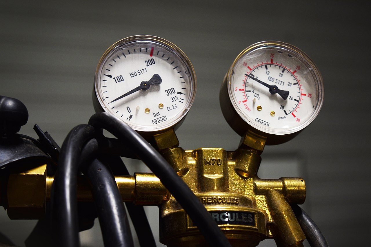
A delivery-pressure gauge is not a flowmeter. Verify gas flow with the normal gas, nozzle, and gas-on condition.
Do not assume every nominal liter is usable. Stable delivery, return rules, and planned changeover can require positive residual pressure.
Preflow, postflow, purging, test welds, leaks, and idle open-flow can consume gas without adding weld length.
Material, filler, appearance, metallurgy, nozzle, and the qualified procedure decide whether argon or nitrogen is acceptable.
How to Calculate Shielding-Gas Cylinder Life
Enter supplier-rated contents and a verified actual flow. The advanced fields turn continuous runtime into a production estimate by including reserve, gas-on fraction, trigger timing, and active welding time per part.
Which Cylinder Number Should You Use?
A supplier may describe a package by water capacity, size code, service pressure, fill pressure, gas grade, or nominal free-gas contents. Only the last item directly enters the simple runtime formula.
Internal vessel volume, not the gas released at standard conditions.
For example: 10 m³, 126 ft³, 304 ft³, or 336 ft³.
Rated contents minus the site-defined reserve and documented losses.
Why pressure alone cannot give an exact answer
A high-pressure gauge helps the operator follow the trend toward depletion. It does not show torch flow. It also does not fully account for temperature, fill tolerance, real-gas compressibility, regulator behavior, or the minimum pressure needed to keep the welding process stable.
When a supplier provides nominal free-gas contents, use that figure. If only water capacity and pressure are available, request the supplier's content table or calculator. Do not multiply 50 L by 200 bar and present the result as an exact usable quantity.

| Label or quote item | Can it calculate runtime? | Correct use |
|---|---|---|
| Free gas: m³, L, or SCF | Yes, after matching the flow unit and deducting the chosen reserve. | Use it directly. Also record purity, supplier, and package code. |
| Water capacity: 40 L, 47 L, 50 L | No. | Ask for the rated free-gas contents at stated reference conditions. |
| Fill or service pressure | Not reliably by itself. | Use for equipment compatibility and trend monitoring; follow supplier data for contents. |
| Supplier size code | No. | Match the code to that supplier's current contents and valve table. |
| Purity or gas grade | No. | Use it to confirm process suitability and cost—not runtime from a stated volume. |
Does Nitrogen Last Longer Than Argon?
If two cylinders truly provide the same standardized volume at the same true flow, they last the same time. Yet real supplier packages and approved process settings can be different, so never compare by gas name alone.
Argon may be selected for process stability, appearance, or alloy-specific reasons. Use the exact supplier package contents and the flow approved for that welding setup. Cylinder color conventions vary by country; identify the gas from its label.
Nitrogen may be acceptable for selected materials and quality requirements, but it is not a universal substitute for argon. Confirm the exact gas grade, material, filler, nozzle, and qualified parameter window before changing gas to lower cost.
How Does Gas Flow Change Runtime?
These values show the calculation, not the correct operating setting. Use your supplier's capacity and the machine's verified flow.
| Supplier or planning example | Rated free gas | At 15 L/min | At 20 L/min | What it proves |
|---|---|---|---|---|
| Metric planning example | 10 m³ / 10,000 L | 11.11 h | 8.33 h | A common calculation example, not a universal 50 L cylinder equivalence. |
| Airgas size-125 argon example | About 126 ft³ / 3,568 L | 3.96 h | 2.97 h | The size code does not replace the listed free-gas amount. |
| Airgas size-300 argon example | About 336 ft³ / 9,514 L | 10.57 h | 7.93 h | A “300” package can contain more than 300 ft³. |
| Airgas size-300 nitrogen example | About 304 ft³ / 8,609 L | 9.57 h | 7.17 h | Same package class does not guarantee the same gas contents. |
| 200 SCF example | 200 ft³ / 5,663 L | 6.29 h | 4.72 h | SCF and L can be converted when reference conditions are compatible. |
All results are rounded continuous gas-on estimates before reserve, preflow/postflow, purge, leaks, and meter error. Supplier examples are product-specific and can change.
Hours = usable m³ × 1,000 ÷ flow in L/min ÷ 60.
Hours = usable SCF ÷ true flow in SCFH.
1 ft³ = 28.316846592 L. Check the standard temperature and pressure basis before comparing supplier data.
Why Gas-On Time Is Not the Same as Shift Time
The cylinder can last longer than one calendar shift when gas is off during loading and inspection. It can also empty faster than laser-on records suggest when preflow, postflow, purge, trials, or leaks are ignored.
Gas starts before the beam. Count it once for every trigger cycle.
Gas flows while the operator travels along the seam.
Gas continues after release as configured by the machine.
Changeover, first-piece trials, and line purge add non-saleable use.
Leaks or an unattended open line consume gas without production.
Convert continuous runtime into a shift estimate
If a cylinder provides 8.33 continuous gas-on hours and gas flows during 40% of elapsed shop time, the simple elapsed-time estimate is 8.33 ÷ 0.40 = 20.8 hours. At an 8-hour shift length, that is about 2.6 shifts before extra losses and reserve.
This calculation becomes useful only when the gas-on fraction comes from the real cell. Time a representative batch or use a correctly configured totalizer. Do not confuse machine duty cycle, operator utilization, laser-on time, and gas-on time; they can be different.
Gas used per completed part
1. Total gas seconds = active weld seconds + starts × (preflow + postflow) + planned purge/test seconds.
2. Gas per part in liters = total gas minutes × verified L/min.
3. Parts per cylinder = usable cylinder liters ÷ gas liters per accepted part.
4. Validate the model against an actual cylinder change or totalizer reading, then update the reserve and reorder point.
How to Measure Actual Shielding-Gas Flow
A stable outlet-pressure gauge can coexist with a leak, restriction, damaged nozzle, wrong scale, or unexpected torch flow. Measure the quantity used in the runtime formula: actual volumetric flow under defined conditions.
Following cylinder pressure and identifying an approaching changeover under comparable conditions.
Does not proveTrue L/min at the nozzle, exact remaining volume, or weld quality.
Showing regulated outlet pressure upstream of the machine's restrictions.
Does not proveActual volumetric flow. A pressure regulator is not automatically a flow-control measurement device.
Reading flow within its specified gas, pressure, temperature, and range.
Does not proveCorrect argon or nitrogen flow when the scale or correction does not match the gas.
Recording accumulated gas use and real consumption by job when selected and installed correctly.
Does not proveThat gas selection, standard conditions, or process settings were qualified.

Verify flow at the condition that matters
Use the approved gas, installed hose, regulator, normal nozzle, and normal gas-on routine. A variable-area flowmeter is calibrated for a defined gas and set of pressure and temperature conditions. If a meter is used with another gas, follow the manufacturer's correction or select a multi-gas device designed for that use.
A matching cylinder connection does not prove that the scale is correct. It also does not prove that the regulator, hose, and fittings are rated for the pressure and process. Confirm every component against the supplier and machine documentation.
Why Does Shielding-Gas Use Increase?
More flow is not automatically better shielding. Excessive velocity can disturb the shielding envelope or hide a nozzle, draft, or maintenance problem. Change settings only through a documented process trial.
Diameter, shape, damage, spatter, and standoff change restriction and effective coverage.
Butt, lap, fillet, corner, and wire-fed joints expose different molten areas.
Gas choice and acceptable results depend on the exact alloy and acceptance criteria.
Beam motion, seam length, speed, and the number of starts change use per part.
Air movement can disturb shielding; address the environment and torch angle before increasing flow.
A clogged nozzle, dirty lens, damaged hose, or leak can make a correct setting ineffective.
Preflow and postflow add fixed consumption to every trigger cycle.
Gas, calibration, pressure, temperature, and standard-volume definitions affect the reading.
Which Gas Supply Package Fits the Shop?
A single cylinder may suit prototypes and light work. Repeated changeovers, several welding heads, or long supplier lead times can justify a bundle, manifold, liquid vessel, microbulk system, or pipeline review.
Simple for low demand and mobile work. Plan secure handling, a backup, changeover time, and gas availability.
Helps continuity when one cylinder empties. Include manifold dead volume, valve sequence, and purge work.
Reduces change frequency for stable higher demand, but needs supplier-compatible handling, access, and storage.
Can suit sustained demand. Capacity, vaporization, pressure, redundancy, installation, and contract terms require a supplier study.
Record gas grade, verified flow, total gas-on minutes, starts, completed acceptable parts, and setup losses.
Use average and peak demand, supplier lead time, backup policy, safe storage limits, and weekend coverage.
Include gas, delivery, rental, handling, changeover labor, purge losses, downtime, and quality impact—not invoice price alone.
Why is the cylinder empty sooner than expected?
Start by comparing actual flow and total gas-on time with the inputs used in the estimate. Do not compensate for an unexplained loss by lowering flow or accepting weaker weld quality.
| Symptom | Likely cause | Confirmation | Corrective direction |
|---|---|---|---|
| Runtime is much shorter than calculated | Higher true flow, wrong gas scale, leak, open valve, extra reserve, or uncounted purge. | Measure flow in the normal gas-on state; review totalizer and approved leak-test results. | Correct measurement, repair leaks, improve shutdown practice, and update the estimate. |
| Quality falls before the gauge looks empty | Regulator behavior, hose restriction, nozzle contamination, wrong gas, or a separate process problem. | Verify flow at the head, gas label, machine alarms, nozzle/lens condition, and weld samples. | Fix the supply or process cause. Do not raise flow blindly. |
| Argon and nitrogen estimates disagree | Different free-gas contents, flow settings, meter correction, timing, or standard-volume basis. | Normalize supplier contents and true flow to compatible units. | Compare like-for-like volume, flow, reserve, and approved procedure. |
| Use jumps after a nozzle change | Different geometry, damage, blockage, installation error, or changed setpoint. | Check nozzle part number and condition; verify flow and a qualified weld sample. | Restore the approved setup or validate the new configuration. |
| Small parts consume too much | Preflow/postflow and frequent starts dominate the gas used per seam meter. | Count trigger cycles and total gas-on minutes in a representative lot. | Improve batching or work sequence where permitted; validate any timing change. |
| Gauge drops fast after startup | Temperature stabilization, pressure behavior, or gauge interpretation. | Compare with a totalizer or timed, verified flow test. | Use pressure as a trend—not the sole cost and capacity measure. |

What Safety Controls Are Required?
Argon and nitrogen can displace oxygen without odor or warning. A leak is especially dangerous in pits, tanks, enclosed rooms, vehicles, or other areas where gas can collect. Provide adequate ventilation and use a site risk assessment to decide whether oxygen monitoring or additional controls are required. In the United States, OSHA defines an oxygen-deficient atmosphere under its permit-space rule as less than 19.5% oxygen.
Keep cylinders upright and restrained during storage and use according to supplier and site requirements.
Close valves when not needed; refit the valve-protection cap when provided before movement.
Move cylinders with a suitable cart. Do not drag, roll loose, drop, or allow cylinders to strike one another.
Regulator, fitting, hose, flow device, and machine inlet must suit the gas, pressure, and connection.
Protect cylinders from heat, physical damage, welding sparks, and direct or reflected laser energy.
Supplier instructions, workplace rules, transport law, fire requirements, and local codes govern the installation.
What Should You Send for a Welding Review?
A useful recommendation begins with the joint and actual demand—not only “argon or nitrogen” and laser power. Oceanplayer Laser can help connect the welding setup, measured consumption, quality target, and supply capacity.
Move from a cylinder-duration estimate to gas selection, operating cost, process settings, and equipment configuration.
Argon and nitrogen cylinder runtime FAQ
How long will a 10 m³ argon cylinder last for handheld laser welding?
It provides about 11.1 continuous gas-on hours at 15 L/min, 8.3 hours at 20 L/min, or 6.7 hours at 25 L/min before reserve and losses. Use the supplier-rated free-gas contents and a verified actual flow for the final result.
Does nitrogen last longer than argon in a laser welder?
Not inherently. Equal standardized volume at equal true flow gives equal calculated runtime. Actual results differ when cylinder contents, approved flow, gas timing, meter calibration, and welding procedure differ.
What flow rate should I use for handheld laser welding?
Use the exact machine manual and qualified welding procedure. Published manufacturer guidance varies, and the correct rate depends on gas, nozzle, material, joint, drafts, speed, and acceptance criteria. Do not use a calculation example as a setpoint.
How do I convert SCFH to L/min?
Multiply SCFH by 28.316846592 and divide by 60. For example, 55 SCFH is about 25.96 L/min. Confirm that both values use compatible standard temperature and pressure conditions.
Can I estimate cylinder life from the pressure gauge?
Use pressure as a trend, not the sole consumption calculation. A rough partial-cylinder estimate is possible at similar temperatures, but supplier-rated contents plus measured flow are more reliable because temperature, compressibility, gauge error, fill tolerance, and reserve affect the result.
Why is my gas cylinder empty sooner than expected?
Common causes are higher actual flow, the wrong meter scale, preflow/postflow, many short starts, purging, trial welds, leaks, unattended open flow, and a larger reserve than the estimate assumed. Measure true flow and total gas-on time for a representative job.
Sources and image credits
Values are planning references, not guaranteed operating results. Check the current supplier data sheet, machine manual, qualified welding procedure, and applicable site rules.
Supplier-specific argon and nitrogen free-gas capacity, pressure, water volume, and connection examples.
Example 10 m³ x47s package at 200 bar; not a universal cylinder equivalence.
Supplier examples showing that cylinder contents vary by size and fill pressure.
Cubic-foot to liter conversion, including 1 ft³ = 28.316846592 L.
Product-specific gas type, purity, inlet-pressure, and minimum-flow guidance.
Representative, model-specific gas-flow starting ranges and process context.
Why rotameters depend on gas, pressure, and temperature calibration conditions.
Pressure-reducing regulator selection, inspection, shutdown, and safe use.
General US compressed-gas cylinder handling, storage, and use requirements.
US permit-space definition of oxygen-deficient atmosphere below 19.5% oxygen.

Hero image, released under CC0 through Wikimedia Commons.

Cylinder-data image, released to the public domain through Wikimedia Commons.

Measurement-section image, licensed CC BY-SA 4.0 through Wikimedia Commons.

Safety-section image, licensed CC BY-SA 4.0 through Wikimedia Commons.
Share the actual material, thickness, joint, nozzle, gas, verified flow, trigger pattern, shift target, and required weld evidence. Oceanplayer Laser can help connect machine configuration, shielding-gas planning, and a representative sample trial.
- Material grade and thickness
- Joint drawing and fit-up
- Machine/head/nozzle
- Gas grade and supplier package
- Verified flow and gas timing
- Parts and shifts per day
- Quality acceptance criteria
- Site and supply constraints