

Reflective metal laser welding guide
How to Laser Weld Highly Reflective Metals Without Back-Reflection Damage
Copper, aluminum, brass and plated parts can return damaging laser energy into the process head, delivery fiber or source. The right response is not one magic angle or power setting. It is a qualified, manufacturer-approved optical system with monitored protection, controlled welding conditions and proof that the joint meets its real duty.
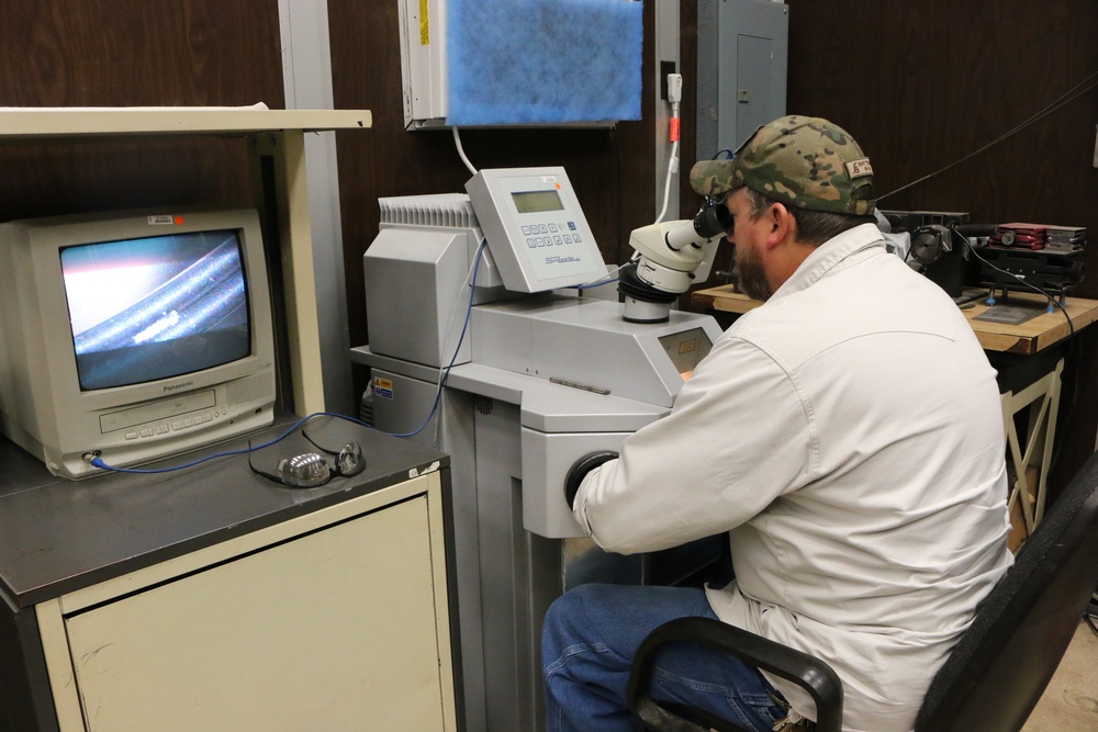
How Do You Prevent Back-Reflection Damage?
Freeze the real workpiece and the complete optical chain before choosing parameters. The trial should connect a known condition to a recommended action, the evidence needed for acceptance and a clear stop boundary.
Include the actual alloy, temper, plating, oxide, cleanliness, geometry, starts, corners and restarts—not only a warm, steady bead.
Confirm the source, delivery fiber, process head, focal optic, protective window, monitoring and enclosure as one application-specific system.
Keep alarm and source logs, inspect protective optics, section the weld and run the functional test—resistance, leak, strength or fatigue—that matches the part.
Stop for unapproved component mixes, recurring return alarms, optic heating or damage, unstable fusion or unexplained penetration and resistance drift.
Start with the physics
What Is Back Reflection in Laser Welding?
When the beam reaches a metal surface, part of the energy is absorbed and part is reflected. On highly conductive metals such as copper and aluminum, absorption at common near-infrared fiber-laser wavelengths can be low before the surface heats and a stable melt pool develops. The returned energy may travel through the process head and delivery path toward components that were designed to send energy forward, not receive a concentrated return. A peer-reviewed copper comparison reported room-temperature absorptivity below 5% at 1030 nm and about 40% at 515 nm for the studied conditions; these values explain a wavelength trend, not a universal production setting.
Visible brightness is a poor guide. A near-infrared beam can be hazardous even when the operator cannot see it. The angle and shape of the part can also redirect energy as the torch moves. Current OSHA laser-safety guidance treats Class 4 direct and reflected radiation as a serious eye, skin and fire hazard. That is why a polished surface, molten pool and changing joint geometry must be treated as dynamic optical conditions, not a fixed mirror.
The practical rule: separate the question “Can the joint absorb enough energy to weld?” from “Can the complete equipment and safety system manage the energy that is not absorbed?” Both must be answered.
Back-Reflection Protection and Laser Safety Solve Different Problems
An enclosure and protective eyewear reduce exposure risk for people. Back-reflection-tolerant source architecture, approved optics and monitoring protect the laser system. One does not replace the other.
This conceptual diagram explains the hazard path only. It does not define a safe angle, return-power limit or retrofit design. Those values are specific to the approved equipment configuration.
Two separate control problems
How Do You Protect People and the Laser Optical Chain?
A strong welding cell treats these as parallel duties. Buying eyewear does not make an open Class 4 process safe, and buying an isolator does not prove the whole delivery system is protected.
Protect People with Enclosure, Interlocks and Access Control
- Use a validated protective housing or enclosure whenever practical.
- Apply interlocks, warning indicators, controlled access and emergency procedures.
- Assess specular and diffuse reflections from the part, fixture and nearby surfaces.
- Select eyewear only through the formal laser safety assessment for the actual wavelength and exposure.
- Capture welding fume close to the process and assess metal- and coating-specific hazards.
Protect the Source, Fiber, Head and Optics from Returned Energy
- Use the exact source, fiber, process head and optic combination approved by the supplier.
- Confirm what return condition is permitted and how it is detected.
- Understand whether the system dissipates returned energy, derates, alarms or shuts down.
- Monitor protective-window condition, focus stability and process signals.
- Requalify after changes to source, fiber, head, focal length, material, coating or joint geometry.
This guide does not provide a universal safe angle, optical-density value, return-power limit or retrofit recipe. Those choices depend on the exact equipment, wavelength, geometry and exposure assessment and belong to the laser manufacturer, qualified integrator and responsible laser safety program.
Where failures begin
When Is Back-Reflection Risk Highest?
Back-reflection risk changes during a weld. Qualification should cover the difficult transitions, not only the stable middle of a good bead.
Before heating changes absorptivity, a clean polished surface may couple less energy and return more of the incident beam.
The optical condition changes rapidly as the surface heats, deforms and develops a molten pool or keyhole.
Fixture error, part angle and seam geometry can move the focal condition or redirect the return path.
Repeated initiation events can behave differently from steady travel, especially after heat accumulates in the fixture.
Spatter or contamination can heat the window, distort focus and create a second failure mechanism that resembles a parameter problem.
How Should Copper, Aluminum, Brass and Plated Parts Be Compared?
“Reflective metal” is a useful screening label, but it is not a welding specification. Use the real grade, surface and functional requirement to decide what the trial must prove.
| Material condition | Recommended starting route | Evidence required | Stop and review when |
|---|---|---|---|
| Copper or copper alloy | Compare a protected near-infrared route with a visible-wavelength route when the joint, available power density and production target justify it. Test cold starts separately. | Start, steady and stop cross-sections; resistance or heat-rise data for electrical joints; alarm logs; protective-optic condition. | Return alarms repeat, the optic degrades, start fusion is unstable or electrical performance drifts without an explained cause. |
| Aluminum alloy | Identify alloy, temper, oxide and fit-up. Control height and focus, then qualify the approved source-to-head system on the real joint. | Penetration and fusion, porosity, distortion, surface-window limits and equipment signals across representative lots. | Material identity is uncertain, oxide/surface variation exceeds the test window, or focus and penetration drift. |
| Brass or bronze | Identify the alloy before selecting a route. Treat reflected energy, volatile alloying elements, fume capture and porosity as separate qualification questions. | Alloy certificate, extraction assessment, porosity/fusion inspection and configuration-level optical approval. | Composition is unknown, fume control is not designed, pores or melt ejection remain unstable, or return events are unexplained. |
| Plated or coated part | Freeze substrate, coating material, thickness and allowed variation. Test the real stack rather than a bare coupon. | Coating specification, cross-sections, functional joint test, surface-window limits and optical-system logs. | The stack is unknown, coating variation changes the result, contamination damages the optic, or acceptance cannot be measured. |
Why “Just Tilt the Part” Is Not a Control Plan
Tilt may change where one reflected ray travels, but production parts contain seams, edges, curvature, fixtures and moving surfaces. An angle that looks favorable at one position can create another path elsewhere. Treat orientation as a process variable to qualify, never as an unofficial substitute for approved source protection and enclosure design.
Defense in depth
What Should a Back-Reflection Protection Plan Include?
A reliable cell does not depend on one accessory. It uses compatible equipment, containment, monitoring, validation and controlled maintenance as a single system.
Manufacturer-approved architecture for expected reflective loading, with defined alarm or energy-management behavior.
Approved fiber, connectors, head, collimation, focus optics and protective windows.
Inspection intervals, cleanliness criteria, temperature or condition monitoring and replacement rules.
Validated housing, access control, interlocks, indicators and a safe response to faults.
Return alarms, source signals, weld signatures, camera data and clear stop criteria.
Requalification triggers for material, surface, geometry, hardware, software and maintenance changes.
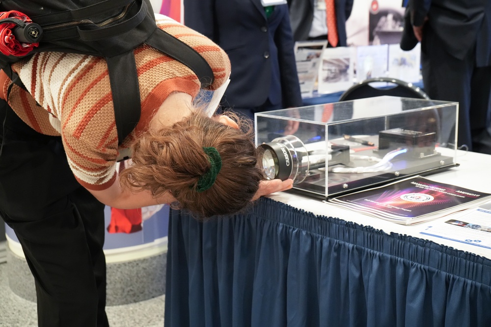
What Configuration-Level Evidence Should the Supplier Provide?
A brochure may say a source is suitable for copper or that a head contains back-reflection protection. That is not enough. The supplier should confirm the exact source, delivery fiber, process head, focal optic, protective window, sensor logic and intended weld condition as one approved configuration.
Manufacturer solutions differ. Some detect a return and shut down. Others are designed to route or dissipate a defined returned load. Neither approach should be assumed from a product family name. Ask what the system permits, what it measures, what happens on an alarm and what evidence supports the claim.
Best purchasing habit: put the approved configuration, alarm behavior, commissioning tests and change-control responsibilities into the quotation and acceptance plan.
Choose the route, then qualify it
Should You Use Near-Infrared, Green, Blue or Beam-Shaped Laser Welding?
A shorter wavelength can improve initial absorption in copper under tested conditions, but it does not make reflected radiation disappear. System protection, enclosure and qualification remain necessary.
| Process route | Why buyers consider it | What must still be qualified | Good starting discussion |
|---|---|---|---|
| Protected near-infrared fiber laser | Broad industrial availability, high power options and mature integration ecosystem. | Cold-start coupling, returned-energy tolerance, source/head compatibility, spatter and penetration stability. | Ask for evidence on the exact reflective material, joint, source and head. |
| Green wavelength | Copper can absorb green light more effectively than common near-infrared wavelengths, supporting a wider or more stable process window in some applications. | Actual alloy, surface, thickness, optical chain, enclosure, productivity and required weld quality. | Compare validated weld results and total cell economics, not absorption alone. |
| Blue wavelength | Another higher-absorption route for copper and some nonferrous applications. | Available power density, joint design, penetration target, production rate and equipment-specific reflected-energy controls. | Use supplier trials on production-like samples. |
| Beam shaping, wobble or multi-beam | May broaden the process window, stabilize coupling or control bead geometry without changing the base wavelength. | Spot distribution, motion logic, seam access, heat input, defects, cycle time and protection limits. | Treat the beam profile and motion recipe as qualified process variables. |
Higher absorption can reduce the fraction of energy returned under a given test, yet the unabsorbed beam can still be hazardous to people and equipment. Compare source protection, service response, process data and qualification evidence alongside wavelength.
Interactive planning aid
What Should Happen Before a Reflective-Metal Welding Trial?
Select the closest application. The recommendation identifies the next engineering conversation; it does not approve a parameter set or replace the equipment manufacturer and laser safety assessment.
Use production-like conditions where possible.
Copper with a bright surface can create a demanding initiation condition. Confirm the entire optical chain before testing, then study starts, steady travel and restarts separately.
- Ask for returned-energy limits and alarm behavior for the exact configuration.
- Include first-part and cold-fixture starts in the test plan.
- Validate electrical resistance as well as fusion and defects.
Prove the complete process
How Do You Qualify Reflective-Metal Laser Welding for Production?
The aim is not merely to make one attractive weld. It is to show that the optical system remains protected and that repeated production joints meet their functional requirement.
Record alloy and temper, thickness, plating or coating, surface condition, joint stack, fit-up and acceptance criteria.
Identify source, wavelength, delivery fiber, process head, focal optic, protective window, monitoring and enclosure.
Study a controlled window that includes cold starts, warm starts, steady travel, corners, restarts and expected process variation.
Record return alarms, source signals, optic condition, focus stability, plume behavior and any protective shutdowns.
Use the checks required by the product: macrosections, fusion, porosity, mechanical tests, leak testing, resistance or fatigue.
Document stop rules and requalification triggers for material, surface, geometry, hardware, software and maintenance.
What Should a Production-Representative Trial Record?
Agree on the sample set, measurement method, unit and pass/fail rule before the laser is turned on. The required tests depend on the drawing, code and product failure mode; the table below is a planning framework, not a substitute for a welding procedure specification.
| Record | Method or unit | Test condition | Pass/fail or review boundary |
|---|---|---|---|
| Complete optical-chain identity | Manufacturer, model, part number and revision for source, fiber, head, focal optic, protective window and monitoring logic. | Record the exact installed configuration before the first powered trial. | Hold the test if any component is unidentified, substituted or outside the supplier-approved configuration. |
| Returned-energy and source response | Manufacturer-defined signal, unit, timestamp and alarm or shutdown code. | Compare cold start, steady travel, stop, restart, corners and expected height/surface variation. | Stop for an alarm or return condition outside the documented limit; do not bypass or repeatedly reset it. |
| Protective-optic and focus condition | Supplier-defined inspection, temperature/condition signal, focus check and part count. | Inspect before, during planned intervals and after the representative run. | Review unexplained heating, contamination, damage, focus drift or shortened window life. |
| Internal weld quality | Macrosections and the NDT or destructive method required by the governing code or drawing; dimensions commonly recorded in mm. | Sample the start, steady section, end/restart and worst credible joint conditions. | Use the written fusion, penetration and imperfection criteria; visual appearance alone is not acceptance. |
| Functional joint performance | Resistance or heat rise, leak rate, load, fatigue cycles or another product-specific measure. | Use the agreed sample count and environmental or load condition. | Pass only the prewritten product requirement; investigate drift even when the bead still looks acceptable. |
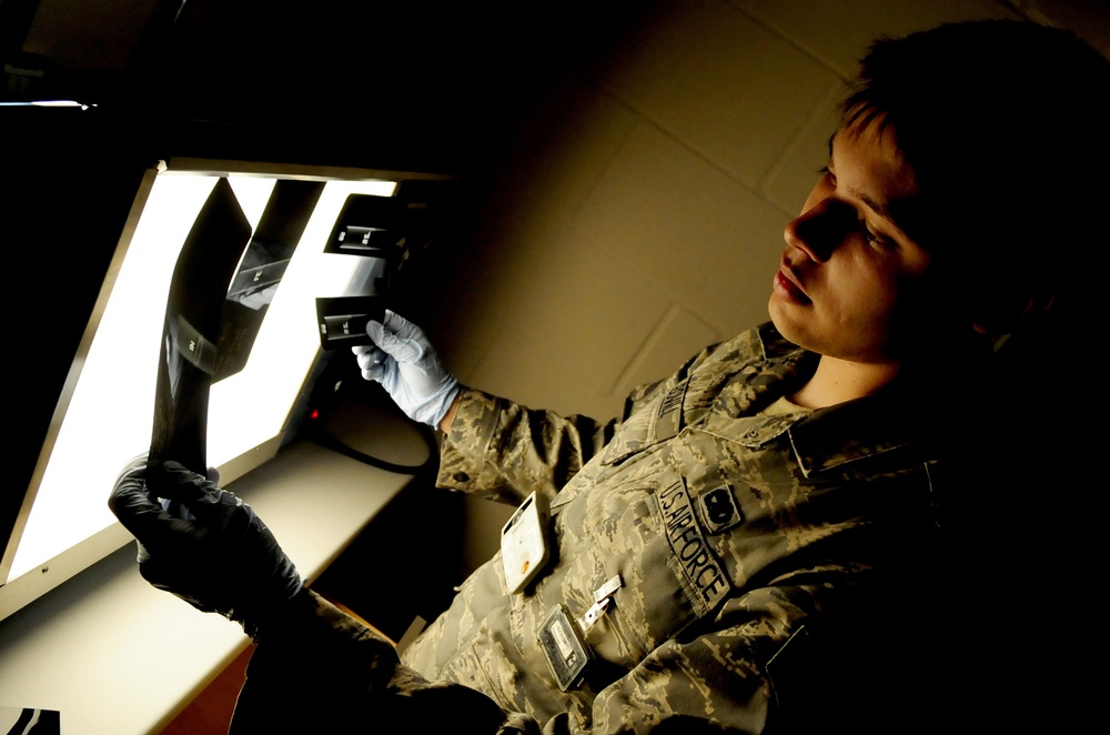
Why a Clean Top Bead Does Not Prove Weld Quality or System Health
Reflective-metal welds can look smooth while hiding incomplete fusion, pores, cracking or inconsistent penetration. The validation method should match the part’s actual failure mode.
- Electrical busbars: resistance, heat rise, fusion area and mechanical integrity.
- Sealed components: leak rate, porosity and dimensional stability.
- Structural joints: penetration, fusion, defects and mechanical performance.
- High-volume production: process signals correlated with destructive inspection.
Illustrative case
Illustrative Case: Copper Busbar Alarms on the First PartsThe cell runs normally after several welds, so the team assumes the laser needs more power at startup. That conclusion is premature.
- Preserve the evidence. Record the exact alarm, source status and process signals instead of repeatedly restarting.
- Compare cold and warm conditions. Check first-part surface, fixture temperature, part height and start logic.
- Inspect protective optics. A degrading window can change focus and add thermal behavior that appears only after cycling.
- Separate bead zones. Section the start, steady zone and stop; do not judge the whole weld from the middle.
- Review the approved envelope. Ask the system supplier whether the recorded return event is within the permitted condition.
- Change one variable at a time. Do not mask the mechanism by increasing power or disabling a protective response.
Troubleshoot without hiding the risk
What Should You Do When Back-Reflection Alarms Appear?
Use symptoms to organize a safe investigation. They are not proof of one root cause.
| Observed symptom | Possible contributors | Safe confirmation path | Do not do this |
|---|---|---|---|
| Return or back-reflection alarm | Cold polished surface, geometry shift, wrong head/source combination, poor focus, changing keyhole or contaminated optics. | Stop under the approved procedure; preserve alarm data; inspect the optical chain; compare the event with the supplier’s permitted condition. | Do not defeat the alarm, repeatedly restart or assume a small angle makes it safe. |
| Intermittent fusion at the start | Low initial coupling, surface variation, gap, height, start ramp or unstable initial melt formation. | Separate cold and warm starts; measure fit-up; inspect start cross-sections; correlate source and weld signals. | Do not raise power before confirming the returned-energy and defect consequences. |
| Spatter or unstable bead | Unstable keyhole, excessive local energy, gap, contamination, beam profile or motion mismatch. | Inspect surface and fixture; review high-speed or process-monitor data; check protective-window condition and cross-sections. | Do not judge only from the top bead or continue until the window fails. |
| Protective window degrades quickly | Spatter path, inadequate gas/nozzle setup, contamination, poor maintenance interval or upstream instability. | Track window life by part count; inspect deposits; verify focus and nozzle geometry with the supplier’s procedure. | Do not treat frequent window replacement as normal without finding the mechanism. |
| No alarms, but penetration changes | Material surface, coating, focus shift, optic heating, seam position, power delivery or fixture drift. | Compare process signals with macrosections and functional tests; audit maintenance and material lots. | Do not assume “no alarm” means the weld is qualified or the optical path is healthy. |
Turn risk into a better RFQ
What Should Buyers Include in a Reflective-Metal Laser Welding RFQ?
“Can this laser weld copper?” is too broad. Describe the part, joint, surface, cycle, quality requirement and complete optical configuration.
For this exact source, delivery fiber, process head, optic and weld condition, what returned-energy condition is permitted, how is it monitored, what happens on an alarm, and what evidence supports the approved configuration?
Continue the engineering decision
Related Oceanplayer Laser resourcesFrequently asked questions
Frequently Asked Questions About Back Reflection in Laser Welding
Can a fiber laser weld copper safely?
Yes, copper can be laser welded, but safe and reliable use depends on the exact source, wavelength, delivery fiber, process head, optics, enclosure, monitoring and qualified process. Do not assume every fiber laser or third-party head is approved for copper’s returned-energy condition.
Does tilting the workpiece prevent back-reflection damage?
Not by itself. Tilt changes one part of the reflection geometry, but seams, corners, fixtures, curvature and motion can redirect energy during the cycle. Orientation can be a qualified process variable, but it should not replace manufacturer-approved protection, enclosure and monitoring.
Does a green laser eliminate back reflection from copper?
No. Green light can be absorbed more efficiently by copper than common near-infrared light under tested conditions, which can improve process stability. Some energy is still not absorbed, so the optical chain, cell safety and weld still require qualification.
Is laser safety eyewear enough for reflective-metal welding?
No. Eyewear is one element selected through a formal hazard assessment. High-power welding should use engineered containment, interlocks, access control and other controls appropriate to the class and exposure. Eyewear also does not protect the delivery fiber or laser source from returned energy.
What should I do if back-reflection alarms are intermittent?
Follow the approved stop and inspection procedure, save the alarm and process data, and compare the event with part surface, start condition, fixture height, joint geometry and optic condition. Ask the supplier whether the recorded event was inside or outside the permitted condition. Do not bypass the alarm or keep restarting to finish the batch.
Does a good-looking weld prove the system is safe?
No. A smooth bead does not prove internal fusion, penetration, porosity, electrical resistance or optical-system health. Validate the joint with the tests required by its service and review equipment signals and optic condition at the same time.

Our team creates practical guides on laser cleaning, welding, marking and industrial automation. We use dated primary sources and clearly labeled planning examples to help manufacturers compare processes, define acceptance evidence and prepare safer equipment trials.
Evidence base
Technical and safety sources- OSHA Technical Manual, Laser Hazards, current U.S. workplace guidance on Class 4 reflected radiation and control measures.
- U.S. FDA: Laser Products and Instruments, product classes and federal requirements.
- U.S. FDA laser-product inspection controls, including protective housing and interlock checks.
- ISO 11553-1:2020, safety requirements for laser processing machines.
- nLIGHT: Back-Reflection Protection, a manufacturer example showing that shutdown and hardware-isolation architectures differ.
- Metals 2023: 515 nm vs 1030 nm copper laser welding, peer-reviewed absorptivity and vapor-capillary comparison.
- Lasers in Manufacturing and Materials Processing: copper welding review, including initiation, absorption and process-stability evidence.
- TRUMPF green-wavelength copper welding data, labeled here as manufacturer evidence rather than a universal rule.
- ISO 15614-11:2025, procedure qualification for laser and electron-beam welding.
- ISO 13919-2:2021, imperfection quality levels for aluminum, magnesium and pure copper laser/electron-beam welds.
Oceanplayer Laser can help you organize a sample brief, compare equipment routes and define the questions that a reflective-metal welding trial must answer. Final safety, optical-chain approval and process qualification remain specific to the selected equipment and site.