

State whether the promise applies at the source, fiber connector, or complete welding-head exit. Also define CW, average, peak, duty cycle, wavelength, and optical configuration.
Handheld laser welder acceptance guide
How to Verify a Handheld Laser Welder’s Actual Output Power Before Acceptance
Yes, you can verify actual output power—but only with a calibrated optical sensor, a defined measurement point, and a controlled Class 4 test. Measure the serial-numbered machine after the agreed delivery path, collect repeated stable readings, and apply the pass/fail rule agreed before the test. A controller display, electrical input, source certificate, or weld coupon alone does not prove the watts delivered by the complete handheld system.
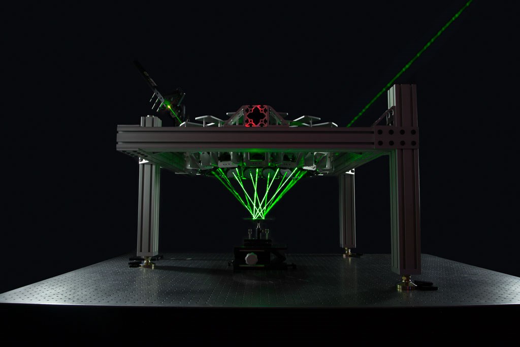
Laser sourceSource rating is not the final result
Delivery fiberInclude the installed production fiber
Welding headHead, optics and protective window
Power sensorMeasure at the agreed acceptance point
Direct answer
01 DefineFix the measurement point
02 ControlUse a safe Class 4 cell
03 MeasureMatch the sensor to the beam
04 DecideInclude uncertainty
What Makes a Handheld Laser Welder Power Test Valid?
A valid test measures optical watts at a written point on the complete machine. It uses a suitable calibrated sensor, a controlled Class 4 setup, repeated stabilized readings, and a decision rule that includes measurement uncertainty. If one of these conditions is missing, the result may be useful for troubleshooting, but it is not strong acceptance evidence.
Rigidly fixture the head, enclose or control the beam path, verify interlocks and emergency stop, manage reflections, and operate remotely under qualified oversight.
Verify wavelength, total power, power density, aperture, beam size, mode, cooling, response, calibration scope, and uncertainty—not just the watt rating.
Collect repeated stabilized readings at agreed setpoints. Use a pre-agreed conformity rule so a near-limit result can be marked indeterminate instead of forced into pass or fail.
MeasurandThe exact quantity being measured—for example, average optical power after the welding head.
Expanded uncertaintyThe reported plus/minus range around a measured result at the stated coverage basis.
Decision ruleThe agreed method for turning the result and its uncertainty into pass, fail, or indeterminate.
Guard bandExtra margin that reduces the risk of accepting a machine whose true output may be outside tolerance.
FATFactory Acceptance Test, completed before shipment at the supplier or test facility.
SATSite Acceptance Test, completed after installation at the buyer’s production site.
Define the measurand
What Does a 1500W Handheld Laser Welder Rating Actually Mean?
A handheld laser welder contains a source, delivery fiber, connectors, collimation, wobble or scanner optics, focusing optics, nozzle parts, and a protective window. Each section can introduce loss or drift.
For most complete-system acceptance tests, the useful question is not “Did the laser source leave the factory as a 1500W model?” It is “How much average optical power does the serial-numbered machine deliver through the installed production head under the agreed mode and condition?”
ISO 11554:2025 provides methods for measuring CW and pulsed laser radiant power, energy, stability, and temporal characteristics. The standard does not choose your commercial measurement point. The buyer and supplier must do that in the specification.
| Claim or measurement point | What it represents | Can it prove complete-system output? |
|---|---|---|
| Source nameplate | Nominal product-family capability. | No. It is not a measurement of the delivered serial-numbered system. |
| Source factory certificate | Source output at the maker’s stated port and conditions. | Useful evidence, but it may exclude delivery-fiber and head losses. |
| Delivery-fiber connector | Power after the source and part of the optical path. | Usually excludes the installed welding head and protective window. |
| Welding-head exit | Power after the complete delivery path and installed window. | Usually the best complete-system measurand when safely measurable. |
| Focus-plane power density | Power per unit area at the workpiece. | Requires total power plus a measured beam size and profile. |
| Electrical input | Mains power used by source, controls, cooling, and auxiliaries. | No. Wall-plug power cannot isolate optical output. |
| Weld depth or speed | Result of the full welding process. | Functional evidence, not calibrated optical watts. |
Swipe the table horizontally to view all columns.
Evidence hierarchy
What Evidence Proves Delivered Optical Power?
Each item below can be useful, but it answers a different question. Strong acceptance evidence ties a calibrated result to the exact machine, optical path, conditions, and decision rule.
Evidence That Does Not Prove Complete-System Output
A controller percentage is a command. Electrical current includes efficiency and auxiliary loads. A weld coupon changes with focus, speed, wobble, gas, fit-up, material, and heat sinking. A source certificate may stop before downstream loss.
Evidence That Supports Complete-System Acceptance
A calibrated sensor log is strongest when it records the exact machine, delivery path, test point, settings, repetitions, conditions, uncertainty, and decision rule. A good coupon remains useful for a separate process test.
1Controller screenshotConfirms a commanded state only.
2Electrical input and source certificateSupport system diagnostics and source identity, but not power after the head.
3Controlled weld couponConfirms process capability for one documented joint and parameter set.
4Calibrated high-power sensor logProvides optical watts at a defined point, with conditions and uncertainty.
Class 4 test boundary
How Can Handheld Laser Welder Output Power Be Measured Safely?
High-power near-infrared laser radiation may be invisible. OSHA identifies Class 4 systems as immediate eye and skin hazards from direct or reflected beams and as potential fire hazards. The machine manual, site risk assessment, applicable law, and responsible laser-safety authority control the physical test.
Minimum controlled-test boundary
This is a planning map, not a substitute for the approved machine-specific procedure or risk assessment.
01Secure the access boundaryRestrict entry, post warnings, and define responsible roles before emission is enabled.
02Fixture the welding headDo not hand-hold the gun during a power measurement. Prevent movement and misalignment.
03Control the beam and reflectionsUse approved enclosure, geometry, termination, and reflection controls for the exact setup.
04Verify cooling and alarmsConfirm source, chiller, detector, interlock, emergency stop, and fire controls.
05Operate remotely and recordUse the approved sequence, stop criteria, and data logging under qualified oversight.
Stop Conditions for a Class 4 Power Test
!
No approved responsible person or procedureDo not improvise a kilowatt-class service test or treat eyewear as the primary control.
!
Uncontrolled beam or reflection routeStop for an open gap, uncertain specular reflection, inadequate termination, or uncontrolled access.
!
Unverified sensor load or coolingTotal watts can be in range while local power density, beam clipping, or water flow remains unsafe.
!
Interlock, emergency stop, alarm, or fixture problemNever bypass a safeguard simply to reach the detector or continue a test after misalignment.
Instrument selection
How Do You Choose the Right Kilowatt-Class Laser Power Meter?
High-power thermopiles and water calorimeters convert absorbed optical energy into a thermal signal. Their safe use depends on more than the maximum-watt number printed on a datasheet.
Confirm the processing wavelength, detector coating, calibration wavelength, and any spectral correction.
Mismatch risk: biased responsivity or absorber damage.Define average power, peak power, pulse energy, duty cycle, repetition rate, and possible overshoot.
Mismatch risk: correct average reading but unsafe peak load.The complete beam must fit inside the active area with alignment margin. Verify the minimum beam size at the absorber.
Mismatch risk: clipping, rim heating, or excessive local density.Check water type, inlet temperature, flow, pressure, alarm, response time, exposure duration, and recovery.
Mismatch risk: drift, overload, coating failure, or false stability.Use a current calibration that covers the relevant range and wavelength. Record instrument resolution, linearity, repeatability, and uncertainty.
“NIST traceable” is not a substitute for a traceable result.Control returned energy, verify full termination, save raw samples and timestamps, and record all sensor alarms.
A photograph of one high value does not prove stability.Commercial sensors illustrate why these limits matter. For example, Coherent’s PM10K+/PM15K+ specifications separately state wavelength range, active area, recommended minimum beam size, power-density limits, water flow, response time, calibration uncertainty, and linearity. Gentec-EO’s water calorimeters calculate incident power from monitored flow and temperature. These are selection examples, not endorsements; the exact current manual controls use.
Pre-test agreement
What Must Buyer and Supplier Agree Before Testing?
Power disputes often begin with two teams testing two different definitions. Review the commercial and technical records first, then lock the machine state, optical path, instrument, tolerance, and decision rule.
If the result controls final payment, warranty, or a dispute, consider a competent test provider or an ISO/IEC 17025-accredited laboratory whose scope covers the required optical power and range.
01
Commercial requirementPurchase order, approved quotation, specification, deviations, rated mode, value, and tolerance.
02
Machine identityMachine, source, fiber, and head models/serials plus controller and firmware versions.
03
Optical configurationFiber length/routing, head/nozzle setup, protective-window part and condition, and measurement point.
04
Meter evidenceSensor and meter serials, calibration certificate, wavelength/range scope, uncertainty, and settings.
05
Safety releaseControlled-area plan, responsible roles, fixture, enclosure/termination, cooling, alarms, and emergency response.
06
Test and decision planSetpoints, repetitions, stabilization, acquisition, uncertainty rule, retest, and disposition authority.
Buyer-ready acceptance clause
Delivered average optical power shall be measured at the agreed point after the complete production welding head and installed protective window, using a calibrated sensor approved for the wavelength, power, power density, beam size, mode, cooling, and exposure. The report shall identify all machine and instrument serial numbers, test conditions, repeated readings, expanded uncertainty, conformity rule, deviations, and final disposition.
Edit the values and limits in the purchase specification.FAT / SAT workflow
How Should a FAT/SAT Output-Power Test Be Run?
This is a procurement and quality framework. The machine and instrument manuals determine the physical setup, distances, exposure time, cooling, and service mode.
Before the Test
Write rated value, mode, wavelength, point, tolerance, repetitions, uncertainty treatment, decision rule, and retest rule.
Record serial numbers, firmware, parameter file, fiber, head, nozzle, and window condition.
Confirm the controlled area, interlocks, remote operation, PPE, termination, fire controls, and emergency stop.
Verify wavelength, power, density, aperture, mode, cooling, calibration, and uncertainty.
During the Measurement
Start machine and sensor cooling per manual. Record temperatures, flow, alarms, supply, and environmental conditions.
With emission safely disabled, check approved fiber routing, connectors, head optics, and protective window.
Zero under actual cooling conditions. Confirm range, wavelength setting, logging, interlock, and alarm behavior.
Rigidly mount the head. Use only the approved aiming or low-power alignment method and verify full beam capture.
Evaluation and Sign-Off
Start low and increase only while cooling, alignment, absorber load, and instrument state remain normal.
Save stabilized samples, mean, min/max, standard deviation, drift, timestamps, and alarms—not just a photo.
Compare command and measured power; assess linearity, stability, repeatability, uncertainty interval, and conformity.
Mark pass, fail, or indeterminate. Attach raw logs, certificates, setup evidence, deviations, and corrective actions.
| Test point | Command | Suggested evidence | Acceptance question |
|---|---|---|---|
| Baseline / zero | Emission disabled | Zero reading and sensor status | Is offset stable and within the instrument rule? |
| Low | 25% or agreed minimum | Three stabilized readings | Does output begin predictably without abnormal offset? |
| Mid-low | 50% | Three stabilized readings | Is measured power consistent with the specified command mapping? |
| Mid-high | 75% | Three stabilized readings | Does heating introduce drift or limiting? |
| Rated | 100% continuous-rated setting | Three or more stabilized readings | Does delivered average power meet the agreed tolerance? |
| Sustained stability | Agreed level and duration | Time-series log, cooling, and alarms | Is power stable without thermal derating? |
| Recovery repeat | Agreed critical setting | Repeat after defined recovery | Is the result reproducible? |
Swipe the table horizontally to view all columns.
Planning calculator
How Do You Calculate Pass, Fail, or Indeterminate?
This interactive example uses a conservative guard-band rule: pass only when the entire reported interval sits inside the specification; fail when it sits completely outside a limit; otherwise mark the result indeterminate.
Pass in this example
1467.7 W
Mean measured power · −2.15% error from reference
Specification interval1425.0–1575.0 W
Measurement interval1437.7–1497.7 W
Sample standard deviation7.5 W
DecisionEntire interval is inside
How to read the default example: the three readings average 1467.7W. The reported interval is 1437.7–1497.7W after applying ±30W expanded uncertainty. Because that full interval remains inside the hypothetical 1425–1575W specification, the example passes. If the interval touched a limit, it would be indeterminate under this rule.
Planning aid only. The ±5% tolerance and 30W uncertainty are hypothetical. A competent test report must define its measurement model, uncertainty, coverage basis, and conformity rule. Do not choose the decision rule after seeing the result.
Beyond the maximum
Why Test the Full Working Range Instead of One Peak Reading?
A machine can touch its maximum briefly yet behave poorly at production settings. Use the command-versus-measurement curve and a time-series record to reveal offset, nonlinearity, hysteresis, and thermal derating.
Linearity Across Commanded Power
Plot commanded watts or percentage against measured watts. Do not assume 50% on screen means exactly 50% optical power unless the manufacturer specifies that mapping.
Repeatability and Thermal Stability
Compare repeated readings and a defined time series. Correlate any downward drift with source temperature, chiller temperature, airflow, sensor cooling, or controller alarms.
Average Power vs Peak Power
For an ideal rectangular waveform, average power is approximately peak power × duty cycle. A 2000W on-state at 50% duty is about 1000W average—not 2000W continuous output.
Controlled troubleshooting
What Causes a Low Laser-Welder Power Reading?
Separate measurement error, configuration error, optical-path loss, and true source underperformance. Never disconnect high-power fiber connectors, open the source, or bypass head interlocks as a shortcut.
| Symptom | Plausible causes | Controlled next check |
|---|---|---|
| All points low by a similar percentage | Wrong wavelength setting, stale calibration, dirty window, fixed optical loss, scaling error. | Verify meter settings and certificate; inspect approved optics; compare with a controlled reference setup. |
| Low only at maximum | Thermal derating, power limit, sensor saturation, insufficient cooling, supply limitation. | Review raw logs, cooling, range, and alarms; repeat only after the cause is controlled. |
| Reading falls during exposure | Source/chiller heating, sensor cooling drift, window heating, or contamination. | Correlate time-series power with temperatures, flow, and alarm state. |
| Large repeat-to-repeat variation | Unstable cooling, moving beam, loose fixture, intermittent connection, inconsistent acquisition. | Lock geometry, verify flow, inspect connection, and review unaveraged samples. |
| Good power but poor weld | Focus, beam profile, wobble, speed, gas, fit-up, reflectivity, or contamination. | Run separate beam-delivery and process qualification. |
| Good source-port result but low head exit | Fiber, head optics, scanner, clipping, window contamination, or damage. | Use qualified service comparison of optical sections under the approved procedure. |
| Meter alarm or rim heating | Beam too small, clipped, misaligned, excessive density, or insufficient cooling. | Stop emission. Correct sensor or geometry with manufacturer guidance. |
Swipe the table horizontally to view all columns.
Two acceptance tracks
Is Optical Output Power the Same as Weld Quality?
No. Run both tests when the contract requires rated optical performance and production weld capability. Keeping them separate makes troubleshooting faster and prevents a convenient coupon from hiding an unproven power requirement.
Optical Output-Power Acceptance
Verifies delivered watts and control behavior at the written optical point.
- Average or peak quantity and waveform
- Setpoint response and linearity
- Repeatability and stability
- Calibration, uncertainty, and conformity rule
Weld-Process Acceptance
Verifies an agreed joint using controlled production conditions.
- Material grade, lot, thickness, and surface
- Joint, gap, clamping, focus, speed, wobble, wire, and gas
- Visual, cross-section, penetration, porosity, mechanical, or leak criteria
- Documented operator and parameter set
Correct optical power with weak welds points toward beam delivery, focus, joint, or process variables. Low measured power with an easy coupon still means the optical requirement has not been proven. For deeper process context, see laser welding power vs penetration depth and the seven weld-seam quality checks.
Final release gate
What Must Be Complete Before Final Acceptance?
Final acceptance should be based on reconstructable test evidence and a completed release review—not a single display photo or a verbal promise.
What the Acceptance Report Must Record
A summary sheet is not enough when it omits setup, raw readings, uncertainty, or deviations. Preserve the information needed to repeat the test and understand why the disposition was issued.
If the seller will not permit a safe independent measurement, settle that before shipment or final payment. Options include witnessed factory testing with buyer-approved equipment, an independent serial-numbered report, or a contractual holdback pending site verification.
Contract requirementValue, tolerance, mode, point, and decision rule.
Machine identityMachine, source, fiber, head, software, and firmware.
MeasurandAverage/peak, wavelength, and exact location.
Optical stateHead/nozzle, window, fiber routing, and condition.
Meter identityModels, serials, calibration, range, and uncertainty.
Setup evidenceDiagram/photos, geometry, fixture, enclosure, and termination.
ConditionsSupply, ambient, source cooling, and sensor cooling.
ProcedureStabilization, setpoints, acquisition, and repetitions.
ResultsRaw readings, mean, min/max, SD, drift, and alarms.
EvaluationError, uncertainty interval, behavior, and category.
ExceptionsAborted runs, replaced optics, retests, and actions.
ApprovalDate, location, names, signatures, and final disposition.
Buyer readiness check
Buyer Release Checklist
Use this on-page checklist during document review. Completion is a planning signal, not a certification or safety approval.
Qualified enquiry
What Information Should You Send for an Acceptance Plan?
Oceanplayer Laser can help you turn the promised power, optical configuration, production task, and buyer risk into a clearer FAT/SAT discussion. Final measurement and safety controls must follow the exact machine, sensor, site, and responsible qualified personnel.
MachineModel, source, head, fiber, cooling, firmware.
Power claimRated/maximum/peak, mode, wavelength, tolerance.
Test pointSource, connector, or complete head exit.
LocationFactory test, site test, or independent laboratory.
InstrumentSensor model, range, cooling, certificate.
Commercial gatePayment, holdback, warranty, or dispute.
Next decisions
Related Laser Welding Guides
Use these published Oceanplayer Laser guides to connect equipment power, cooling, process settings, operator protection, and weld evidence.
FAQ
Frequently Asked Questions About Handheld Laser Welder Output Power
These answers support planning only. Use the exact machine manual, sensor manual, approved procedure, and site safety requirements for the physical test.
Can I test laser welder output power with an electrical power meter?
No. A mains analyzer measures total electrical input to the laser source, controls, cooling system, and other loads. Efficiency varies, so electrical input cannot independently establish optical output. It is supporting evidence for supply or efficiency diagnostics, not the acceptance measurement.
Can I aim the handheld welder directly at a thermopile sensor?
Only when the exact sensor, geometry, fixture, enclosure, cooling, and procedure are approved for that beam. Total power may be within range while local power density or clipping damages the absorber. The head must be rigidly fixed, and a qualified person must verify the controlled setup.
Should power be measured before or after the protective window?
For complete-system acceptance, measuring after the installed production protective window usually gives the most useful delivered-power result. The contract may define another point. Record the window part number and condition because contamination or damage changes transmission.
How many power readings are needed?
There is no universal count. Three stabilized readings per agreed setpoint are a practical minimum in many plans, but sensor response, machine stability, required confidence, and commercial risk may justify more repetitions or a time-series test. Define the count before testing.
What tolerance should I use for a 1500W handheld laser welder?
There is no universal percentage. Use the manufacturer’s warranted delivered-power specification or a negotiated tolerance that defines mode, measurement point, stabilization, instrument uncertainty, and decision rule. The ±5% value in the calculator is hypothetical.
What if the mean is inside tolerance but uncertainty crosses the limit?
Under a conservative guard-band rule, classify the result as indeterminate rather than pass. Improve the measurement, investigate setup and repeatability, retest, or apply another rule agreed before the results were known.
Technical basis
Sources and Technical Review
Standards, official safety guidance, measurement-science references, and current manufacturer documentation were reviewed for this guide. Always confirm the exact editions and manuals required by your contract and jurisdiction.
IEC 60825-1:2014Laser product classification and safety requirements
OSHA Laser HazardsClass 4 direct, reflected, eye, skin, and fire hazards
U.S. FDA Laser Products and InstrumentsU.S. laser product responsibilities and regulations
ISO/IEC 17025:2017Competence, impartiality, and consistent operation of laboratories
ILAC G8:09/2019Decision rules and statements of conformity
NIST Technical Note 2156Metrological traceability and measurement uncertainty
Miller OptX Safety & SetupCurrent manufacturer information for handheld laser-welder safety and setup
NIST High-Power Laser ApplicationsMeasurement challenges and methods for high-power laser metrology
Coherent PM10K+ / PM15K+High-power sensor selection variables and specifications
Gentec-EO Water CalorimetersHigh-power calorimetric measurement principle