

Laser cleaner chiller guide · Selection + acceptance
5 Laser Cleaner Chiller Specs to Verify Before You Buy
A chiller is suitable only when its cooling capacity, source-side temperature, flow and pressure, coolant, and alarm response all match the exact laser system at the real duty point. Do not approve it from a label such as “for a 1500W laser.” Require the source and head manuals, chiller performance data, and a representative acceptance run.
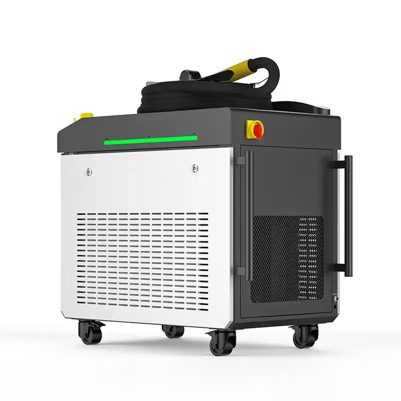 Verify the source, head and cooling loop as one system.
Match the complete cooling loop—not a marketing wattage.
The chiller, hoses, fittings, filter, laser source, cleaning head, room conditions and control logic work as one system. A good match keeps the source inlet inside the manufacturer’s limits during the hottest, longest representative job.
Use the rated conditions, maximum ambient temperature and real duty cycle.
“Colder” is not automatically safer or more stable.
Read the pump curve against the resistance of the installed loop.
Follow the exact source and chiller manuals, alarms and site conditions.
Can you approve the proposed laser chiller?
Use this screen before comparing price. A “review” result means the quotation is incomplete; a “stop” result means the system should not enter production until the mismatch is resolved and verified.
| Condition | Recommendation | Evidence required | Stop boundary |
|---|---|---|---|
| Capacity is shown at your setpoint and hottest ambient | Continue to hydraulic and control checks. | Capacity curve or written duty-point data, complete heat-load list, and planned duty cycle. | Stop if the supplier gives only a “matches laser wattage” label. |
| Required flow reaches the laser source through the installed loop | Confirm pressure stays inside the source limit. | Pump curve, hose and fitting layout, source flow range, and inlet-pressure limit. | Stop if maximum pump flow is presented as source-side flow. |
| Coolant and temperature follow both manuals | Write the fluid, setpoint band, filter, and service interval into acceptance documents. | Exact source and chiller manual revisions plus wetted-material compatibility. | Stop if the proposed fluid conflicts with either manual or creates condensation risk. |
| Representative operation stays stable and alarms stop the laser safely | Save the readings as the maintenance baseline. | Timed inlet/return temperature, flow, pressure, ambient condition, alarm test, and configuration record. | Stop if alarms are bypassed, values drift outside limits, or the test is only an idle run. |
Swipe horizontally to view the full approval screen.
Start with the system
A laser chiller is part of a closed thermal loop.
The laser source converts electrical power into useful laser output and waste heat. The cleaning head and optics may also need temperature control. Coolant carries that heat back to the chiller, where a heat exchanger and refrigeration circuit reject it to the room or to facility water.
This is why the nameplate alone cannot prove compatibility. The system must move enough heat and coolant while staying inside temperature, pressure, cleanliness and environmental limits.
Hoses, quick couplings, elevation, filters and branches all change the operating point.
The five-spec decision map
Which laser cleaner chiller specs decide compatibility?
Read all five together. A chiller can have enough nominal capacity yet still fail because flow collapses through a long hose, the setpoint creates condensation, or the coolant is incompatible with the laser source.
Can the unit remove the combined heat load continuously at the planned water temperature and worst room condition?
Can it hold the permitted inlet temperature without excessive drift, cycling or condensation?
Does the required flow reach the source after every hose, fitting, branch and filter adds resistance?
Does the circuit layout, fluid, filter, seal and wetted material match both manufacturer manuals?
Can the chiller breathe, power up, alarm, interlock and be serviced in the real production location?
| Published example | Model-specific values | What the example proves | What it does not prove |
|---|---|---|---|
| TRUMPF TruFiber S | Cooling water: 25 ± 2°C; operating ambient: 5–45°C. | Water and ambient limits belong to the exact laser model. | These values are not a universal setting for every fiber laser. |
| Coherent Diamond J-2 | Up to 3.0 kW heat removal; 5.7 L/min minimum flow; coolant inlet above dew point. | Capacity, minimum flow, hose size, filtration, and dew point can all be acceptance inputs. | A different source or cleaning head may require different values. |
| TEYU CWFL-3000 | Published ±0.5°C stability, dual circuits, and model-dependent rated flow and pump pressure. | A chiller model can have several electrical variants and operating values. | A catalog match does not replace checking the installed source-side loop. |
Swipe horizontally to compare the published examples.
Spec 01 · Cooling capacity
Ask for capacity at your actual duty point.
Cooling capacity is the rate at which the chiller can remove heat under stated conditions. It is not the same as the laser’s optical output, and the machine label does not reveal every thermal load.
Capacity can change with ambient temperature, water setpoint, condenser airflow and refrigeration design. A rating measured in a cool test room may not represent an enclosed fabrication shop in summer. Ask the supplier to state the water temperature, ambient temperature and test standard behind the rating.
- Combine the laser-source and cleaning-head loads required by the system documentation.
- Use the longest representative cleaning cycle, not a short showroom demonstration.
- Include the hottest expected room or outdoor enclosure condition.
- Protect condenser clearance so hot exhaust cannot return to the air inlet.
Use the heat-balance equation as a diagnostic check.
The equation helps a technician estimate heat movement during commissioning. It does not replace the laser manufacturer’s required cooling load or the chiller performance curve.
No operating condition, reserve or loop detail is defined.
Prefer a curve or written duty-point data.
Trend the source inlet and return, not only the display.
Check airflow, fouling, hot-air recirculation and true heat load.
Spec 02 · Temperature control
Setpoint, stability and dew point are not the same number.
Use the temperature range stated by the exact laser-source manual. Some industrial laser documents specify a narrow cooling-water band and non-condensing conditions, but those values are model-specific—not universal rules.
The available controller range can be wider than the temperature the laser source permits.
This describes variation around the target under defined conditions, not display resolution.
A stable sensor can still be offset. Verify critical readings with a suitable calibrated instrument.
Long hoses and warm surroundings can make the inlet different from the chiller’s internal sensor.
If coolant-cooled surfaces fall below the local dew point, water can condense on hoses, fittings, electronics or optics. Manage room humidity, temperature and insulation as one decision. Follow the source manual’s non-condensing requirement.
Spec 03 · Flow and pressure
The pump’s maximum flow is not the flow at the laser inlet.
A pump curve shows how available head changes with flow. The installed loop has its own resistance curve. Their intersection is the operating point. Longer or narrower hoses, additional elbows, quick couplings, filters and small internal passages move that point.
Find the operating point
Conceptual diagram only. Obtain the real pump curve, required source flow range and allowable inlet pressure before approving the installation.
What to request
- Pump curve for the selected voltage and fluid.
- Minimum and maximum source-side flow.
- Allowable source inlet pressure and pressure drop.
- Hose size, maximum planned length, elevation and connection type.
What to verify on the machine
- Remove trapped air and confirm the filter is clean.
- Measure as close as practical to the source inlet and return.
- Check whether a display value comes from the pump outlet or the laser circuit.
- Do not increase pressure beyond the source limit simply to chase more flow.
Spec 04 · Circuit and coolant compatibility
Copy the manufacturer’s fluid rule exactly.
Generic advice such as “always use distilled water” or “always use deionized water” is not dependable. Laser manufacturers can specify different conductivity, resistivity, pH, hardness, particulate, additive and change-interval limits. The exact source and chiller manuals control.
One controlled loop serves the approved heat loads. It can be simpler, but each added branch changes flow balance and contamination risk.
Use only when: the machine documentation confirms the combined load, circuit arrangement, fluid and flow balance.
Separate temperature or flow circuits can protect components with different needs. “Dual loop” is useful only when it matches the specified plumbing.
Do not assume: every laser cleaner needs two loops, or that two loops may share any coolant and setpoint.
Water quality affects more than the chiller.
Deposits, corrosion products, biological growth and incompatible additives can change heat transfer, block narrow passages, attack seals and create electrical risk. Confirm wetted materials, fitting metals, hoses, filters and approved biocide or antifreeze rules. For the practical maintenance side, see why water quality matters in a laser chiller.
Spec 05 · Environment and protection
A correct chiller can still fail in the wrong installation.
Evaluate the actual production area, electrical supply, airflow and alarm response before delivery. Treat remote contacts and interlocks as part of the safety and reliability design—not optional accessories.
Confirm temperature, humidity, dust, altitude, freezing risk, outdoor exposure and the enclosure around the machine.
Verify voltage, phase, frequency, full-load current, breaker, cable, grounding and local electrical requirements.
Map high/low temperature, flow, level, pump, compressor and communication faults to a safe laser stop.
Leave room for condenser cleaning, filter service, draining, filling, log retrieval and replacement parts.
Cool air reaches the condenser and hot exhaust can leave the work area.
Exhaust hits a wall or enclosure and returns to the inlet, reducing available capacity.
Choose the architecture
Four common ways to manage the heat.
No architecture wins in every shop. Compare installation space, ambient control, service access, noise, mobility, facility-water quality and the laser maker’s approved configuration.
The cooling system is built into the laser cleaner. It can simplify installation and mobility, but service access and thermal reserve may be less visible to the buyer.
Best fit: validated packaged systemsA recirculating unit rejects heat to room air. It is flexible, but needs clean condenser airflow, sufficient clearance and a room that can absorb the rejected heat.
Best fit: most indoor standalone systemsA secondary heat exchanger transfers heat to facility water. It can reduce local hot air, but adds water-quality, pressure, availability and plant-infrastructure requirements.
Best fit: controlled production facilitiesTwo managed circuits serve different components or temperatures. It adds capability and complexity; confirm how each loop is sensed, pumped, filtered and alarmed.
Best fit: documented multi-load systemsEight-step acceptance
Commission the loop before production depends on it.
A short idle check cannot expose every problem. Run the laser cleaner through a representative thermal duty and save a baseline that maintenance can compare later.
This also helps separate a cooling problem from a laser, process or sensor problem when alarms appear months later.
Record the exact source, head, chiller and machine model plus revision-controlled requirements.
List capacity, inlet temperature, flow, pressure, fluid, environment and alarm criteria.
Check hose routing, bend radius, fittings, clearance, exhaust direction, voltage and grounding.
Use approved fluid and procedure. Remove trapped air and check leaks, level and filter condition.
Confirm inlet temperature, return temperature, flow, pressure, supply voltage and sensor location.
Trend values through the longest realistic cycle at the planned power and ambient condition.
Use the OEM-approved method to verify alarms, remote contacts and safe laser shutdown.
Keep readings, fluid batch, filter state, ambient condition and photos for later troubleshooting.
Troubleshooting matrix
Start with the symptom, then test the likely cause.
Do not change several settings at once. Record conditions, make one controlled change, and compare the result with the commissioning baseline.
| Symptom | Likely checks | Useful evidence | Do not jump to |
|---|---|---|---|
| Temperature rises only on long jobs | Actual heat load, ambient temperature, condenser fouling, exhaust recirculation, refrigerant-side performance | Source inlet/return trend, room temperature, power and duty cycle over time | A colder setpoint before capacity and airflow are understood |
| Low-flow or source alarm after hose changes | Hose diameter and length, quick couplings, closed valve, filter restriction, trapped air, elevation | Pump curve, source-side flow and pressure, before/after hose configuration | A larger pump that could overpressure the source |
| Chiller display looks stable; source inlet does not | Sensor location, long warm hose, poor insulation, mixing branch, calibration offset | Independent readings at chiller outlet and laser inlet | Assuming the front display equals the source temperature |
| Repeated high-temperature alarm in summer | Maximum ambient rating, blocked condenser, dusty fins, enclosure heat, inadequate clearance | Inlet-air and exhaust-air temperatures plus site photographs | Resetting the alarm without restoring heat rejection |
| Coolant changes color or particles appear | Fluid compatibility, corrosion, mixed metals, hose breakdown, biological growth, filter loading | Fluid history, conductivity/pH if required, filter inspection and wetted-material list | Adding an unapproved chemical or mixing fluids |
Swipe horizontally to view all troubleshooting columns.
Three shop-floor scenarios
Why do chiller problems appear only in production?
Most useful check: compare the quoted capacity condition with the hottest room temperature, real cleaning duty and condenser inlet air. Hot exhaust trapped around the unit can consume the expected reserve.
Most useful check: plot the changed loop against the pump curve. New quick couplings, a smaller hose or an air pocket may raise resistance enough to reduce source-side flow.
Most useful check: calculate the local dew point and inspect cold surfaces. Restore a non-condensing temperature margin according to the source manual and site controls.
Safety hard gate
Never defeat a cooling alarm to keep cleaning.
A flow or temperature alarm can be evidence that the laser source is outside its safe operating window. Bypassing it may turn a repairable hydraulic or airflow problem into expensive source damage or a wider electrical hazard.
Verify alarm contacts stop or inhibit laser emission in the intended safe state.
Do not open energized enclosures or improvise live measurements without authorization and training.
Depressurize, cool and isolate the circuit before opening fittings, filters or pumps.
Cooling checks do not replace beam enclosures, access controls, PPE, fume capture or process-specific training.
Procurement checklist
Send an RFQ that a supplier can engineer.
Good RFQ data reduces guesswork and makes offers easier to compare. Ask each supplier to respond to the same duty point and acceptance criteria.
Include model, revision, rated power and manufacturer cooling requirements.
Request performance at setpoint, maximum ambient, intended load and duty cycle.
State setpoint, allowable inlet band, stability need and non-condensing condition.
Give hose diameter/length, elevation, fittings, branches, required flow and pressure.
Confirm water quality, additives, wetted materials, filter and change interval.
Give ambient range, humidity, dust, altitude, location and electrical supply.
List sensors, codes, remote contacts, interlock logic and safe-stop behavior.
Ask about filters, spares, refrigerant service, logs, warranty and local support.

Technical references
- TRUMPF TruFiber S technical flyer — supports the model-specific cooling-water and operating-ambient examples used in this guide.
- Coherent Diamond J-2 preinstallation manual — supports the heat-removal, minimum-flow, hose, filtration, and above-dew-point examples.
- Raycus continuous-wave fiber laser user guide — supports the need to set cooling-water temperature for the environment and prevent condensation.
- TEYU CWFL-3000 official product data — supports the published dual-circuit, stability, rated-flow, and pump-pressure example.
- U.S. Department of Energy, Improving Pumping System Performance — pump and system-resistance fundamentals.
- Grundfos pump-curve guide — relationship between flow, head and system characteristics.
- OSHA hazardous-energy control and OSHA laser hazards guidance — service isolation and laser-system controls.
Before you buy or recommission
Send the source model, duty cycle and site conditions—not just the laser wattage.
Oceanplayer Laser can review the cleaning application and help define the cooling, power and machine configuration that should be validated before production.