

What Is the Best Wavelength for a Handheld Laser Cleaning Machine?
For most industrial metal-cleaning buyers, the practical comparison is not simply 1064 nm versus 1080 nm. It is a complete pulsed or continuous-wave system matched to the real coating, substrate, finish limit, geometry, production rate and safety controls.
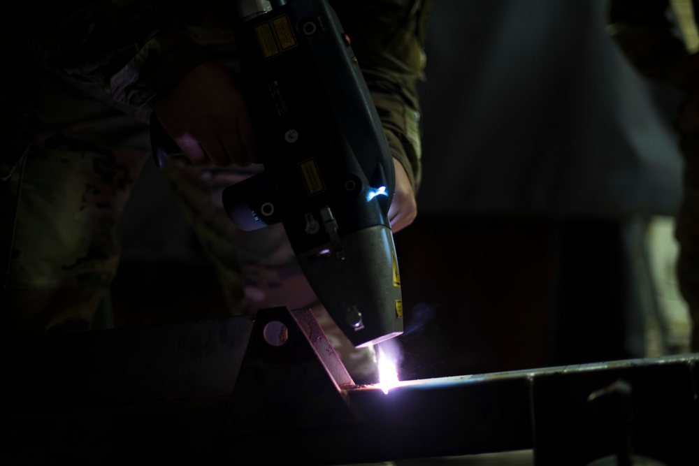
Published handheld systems commonly specify about 1.06–1.08 µm.
Delivery, beam profile, scanning and heat accumulation often create the larger process difference.
Measure removal, substrate condition and good area or good parts per total hour.
Stop when residue remains or the substrate crosses its agreed finish, heat or damage limit.
Start with the required result. Use wavelength and machine specifications to explain and reproduce an accepted trial.
Is 1064 nm Better Than 1080 nm for Laser Cleaning?
No—not as a general rule. When two near-infrared systems clean the same representative surface, pulse or CW delivery, beam profile and scan strategy may create a larger difference than 1064 versus 1080 nm. Wavelength still matters when the layer and substrate have different absorption or damage behavior.
Wavelength is the distance between repeating points in the light wave. It affects optical-component compatibility, reflection and the energy absorbed by the unwanted layer and base material. It belongs in the technical record, but it is not a complete process specification.
Current product examples explain the confusion. JPT lists a 1064 nm pulsed MOPA source. IPG publishes nanosecond pulsed sources at 1064 nm and CW source families around 1070 or 1075 nm. Raycus publishes a CW source at 1080 ± 5 nm. Rocklin lists a 1064 nm pulsed cleaner and separate CW cleaners at 1080 ± 10 nm. These are model specifications—not universal pulsed-versus-CW definitions.
Relative position only. The graphic does not show absorption, pulse behavior, beam quality or cleaning performance.
The optical wavelength emitted by the source, normally stated in nanometers (nm).
A source that delivers energy in short packets separated in time rather than as one continuous beam.
A source that delivers optical power continuously while the head or scan pattern moves across the surface.
Master oscillator power amplifier: a pulsed source architecture that may offer a wider adjustable pulse map.
Energy delivered per illuminated area, commonly expressed as joules per square centimeter for a pulse.
The settings that remove the unwanted layer while keeping the substrate inside its acceptance limits.
What Wavelength Affects
Wavelength affects optical-component compatibility, beam delivery, reflection behavior and absorption by the contaminant/substrate pair. Research comparing 1064, 532 and 266 nm for copper-oxide removal found different removal thresholds and surface effects. This is why a wavelength conclusion from one layer/material pair should not be copied to another.
What Wavelength Does Not Prove
It does not prove pulse energy, pulse width, frequency, beam shape, usable scan field, focus tolerance, handpiece quality, cooling capacity, coating selectivity, substrate safety or production throughput. Those items require the exact source map and a documented test on the actual workpiece.
Why Do Near-Infrared Pulsed and CW Cleaners Perform Differently?
Two cleaners can work at nearly the same wavelength yet produce very different surface effects because energy arrives differently and the scanner distributes it differently.
How Pulsed and MOPA Sources Deliver Energy
Pulsed output may come from Q-switched or MOPA source designs. The source stores and releases energy in short events, so peak power can be high even when average power is lower than many high-throughput CW systems. This can create a useful window for local rust, oxides, molds, tooling and finish-sensitive work.
Some MOPA sources provide wider adjustment of pulse width and repetition rate, but valid combinations remain model-specific. MOPA is not a third operating mode beside pulsed and CW. Pulsed output also does not automatically prevent heating or damage: overlap, dwell, pulse energy, spot, absorption and pass count still control accumulated exposure.
- Record pulse energy, width and frequency together.
- Control spot, overlap, line spacing and passes.
- Inspect the exposed substrate after each screening step.
How Continuous-Wave Sources Deliver Energy
A CW cleaner applies a continuous moving heat source. Higher average power can support heavy rust, scale, paint or large areas on a robust part, but heat can accumulate at edges, slow travel zones and repeated passes.
The result depends on delivered power, travel speed, scan pattern, field width, focus, standoff, passes and cooling. A high headline wattage does not prove usable output, and a module datasheet does not prove the completed handheld system’s performance.
- Time the complete cycle, not beam-on travel alone.
- Inspect heat tint, roughness, pitting and re-oxidation.
- Verify duty cycle after the machine reaches operating temperature.
E = Pavg / fPulse energy relates average power and repetition rate when the source map permits it.F = E / AFluence is pulse energy divided by illuminated area; use the real beam definition.Overlap = 1 − v/(f·d)Along-track pulse overlap depends on speed, frequency and spot dimension.Good output = accepted area / total timeInclude setup, handling, extraction, inspection and routine maintenance.Which Laser Cleaner Should You Test for Your Application?
Choose the closest conditions. The tool recommends a first comparison route, the evidence to collect and the point where the trial should stop. It does not replace a sample test.
The selected job places more weight on selective removal and surface control than raw area rate.
This planner screens the first test route. It does not calculate safe laser settings, certify a process or predict production rate.
How Do the Material, Contamination and Required Finish Change the Choice?
Use this table to choose what should be tested first. It is a planning guide, not a substitute for qualification.
| Condition | First comparison route | Evidence required | Stop or failure boundary |
|---|---|---|---|
| Molds, tools or a finish-sensitive metal surface | Test a pulsed or MOPA handheld cleaner first with controlled spot and scan settings. | Before/after surface inspection, roughness or finish check, protected-edge check and timed accepted output. | Stop for pitting, melting, texture loss, unacceptable color or incomplete residue removal. |
| Light rust, oxide or weld preparation | Compare pulsed and CW if both can meet the required cycle and downstream quality. | Residue test plus weld, coating or adhesion result on several representative samples. | Reject a bright-looking surface that fails the downstream test or changes the base metal beyond the limit. |
| Heavy rust, mill scale or thick coating on robust steel | Test CW first for area rate; add a pulsed comparison where selectivity or edge control matters. | Coating thickness range, accepted square meters per hour, heat/roughness check and plume-capture performance. | Stop for heat tint, re-oxidation, distortion, pitting, unsafe plume or repeat passes that erase the rate advantage. |
| Pre-bond or pre-coat surface preparation | Test a controlled pulsed/MOPA process first unless a CW trial proves the same surface function. | Adhesion, wettability, cleanliness or process-specific performance—not appearance alone. | Reject any recipe that looks clean but produces unstable adhesion, residue or excessive roughness. |
| Large installed structures or field work | Test the complete mobile cell: cleaner, cable, handpiece, extraction, barriers, handling and inspection. | Real reach, operator load, setup time, site power, safe access and accepted output over a representative area. | Stop when access, reflection control, extraction or operator fatigue prevents repeatable safe work. |
If the substrate or coating contains an unknown alloy, plating, lead, chromium, polymer or other hazardous component, identify it before the trial and involve qualified safety personnel.
Which Handheld Machine Features Affect the Cleaning Result?
A good source can still produce a poor field result when the handpiece, cable, scanner, optics, cooling or recipe controls do not fit the job.
Handpiece, Cable and Operator Control
Record handpiece mass and balance, grip, trigger logic, cable length, bend resistance and overhead fatigue. Confirm that standoff and head angle can be held on edges, radii and difficult access points.
- Time a realistic working period.
- Include PPE and extraction hose placement.
- Check cable drag around the actual part.
Scan Field, Focus and Protective Optics
Ask for usable—not only nominal—scan width. Check pattern uniformity, line spacing, focus tolerance, standoff range and field behavior at the edges. Inspect protective-window life in the real plume.
- Verify the field on a flat and curved sample.
- Record lens and window part numbers.
- Define inspection and replacement intervals.
Cooling, Duty Cycle and Recipe Control
Test after the source, chiller or air-cooled package reaches normal temperature. Confirm alarm behavior, restart conditions, recipe storage, parameter permissions and how a source or optics change is controlled.
- Run the intended shift duty pattern.
- Repeat an approved recipe after restart.
- Require change notification for critical components.
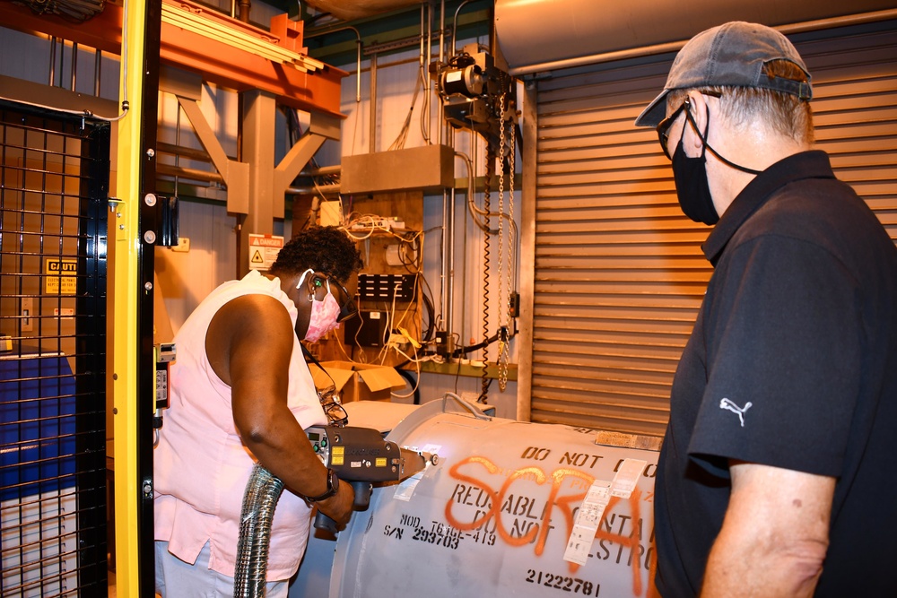
A clean square on a flat sample proves only that one combination worked once. Production parts add edges, holes, radii, vertical areas, changing angles, coating variation, heat accumulation and operator movement.
Keep beam-on removal time separate from total cycle time. Include setup, repositioning, source-capture movement, inspection, window cleaning, recipe changes and ordinary interruptions. The useful number is accepted area or accepted parts divided by the complete measured time.
What Is a Safe Laser Cleaning Process Window?
The process window lies above the exposure needed to remove the unwanted layer and below the exposure that causes unacceptable substrate change.
Rust, paint, oil or oxide remains. Adding power may hide a focus, overlap, chemistry or geometry problem.
The target layer is removed at an accepted rate and the required finish or downstream function is preserved.
Heat tint, oxidation, roughening, pitting, melting, distortion or other prohibited change appears.
Pulse energy, width, frequency, spot, overlap, scan speed, line spacing, focus, passes and heat flow work together. A recipe from another alloy, coating thickness, lens or scanner is only a starting hypothesis. It must not be treated as a safe production setting.
How Should You Test a Handheld Laser Cleaner Before Buying?
A useful trial should produce a qualified result, a traceable configuration and a realistic rate—not a short demonstration chosen to look impressive.
Define the Acceptance Endpoint
Write down what must be removed, what may remain and what must not change. Use a method that matches the next operation: visual reference plus residue check, roughness, coating adhesion, weld quality, dimensional limit, chemistry or another relevant measure. Define the total cycle boundary before timing begins.
Test Representative Parts Under Production Conditions
Include normal and worst-case coating thickness, corrosion severity, oil, substrate grade and geometry. Use the intended handpiece, cable, lens, extraction, power supply and duty cycle. Repeat across operators, positions and several parts after the machine is warm.
Record the Configuration and Accepted Throughput
Record source maker and model, wavelength, architecture, power map, pulse settings where applicable, scan field, spot or focus method, pattern, standoff, passes, head, optics, cooling, extraction and software recipe. Report good area or good parts per total hour after inspection.
Material, contaminant, range of conditions, geometry, access and required final surface.
Normal parts, worst cases, edges and features that control production difficulty.
Change one variable at a time and inspect removal and substrate change separately.
Include handling, extraction, repositioning, inspection and normal maintenance.
Use multiple parts, positions and operators after the system reaches normal temperature.
Store the recipe, machine configuration, measurements, images and failure boundaries.
How Do You Troubleshoot Poor Laser Cleaning Results?
| Observed result | Likely direction | Check before adding power | Failure boundary |
|---|---|---|---|
| Streaks or incomplete tracks | Uneven spatial delivery | Focus, standoff, head angle, scan width, line spacing, overlap and operator travel. | Do not accept a recipe that depends on hidden manual rework. |
| Heat tint, pitting, roughness or melt | Exposure above the surface limit | Reduce dwell or passes; review pulse energy, width, frequency, spot, speed and pattern. | Stop when the agreed finish, roughness, dimensions or metallurgical condition is exceeded. |
| Center cleans but corners remain | Field or motion nonuniformity | Scanner acceleration, field calibration, focus at edges, part angle and usable scan area. | Reject nominal width that does not produce accepted cleaning across the full field. |
| Result drifts during a shift | Optical, thermal or incoming variation | Protective window, source output, cooling, cable, focus and contaminant thickness. | Do not qualify until the warm-state result repeats across the intended duty cycle. |
| Heavy plume or redeposition | Weak capture or rapid material decomposition | Capture position, airflow, filtration, coating hazards, scan direction and removal rate. | Stop if contaminants escape the controlled area or the waste stream is not understood. |
How Should Handheld Laser Cleaning Be Controlled Safely?
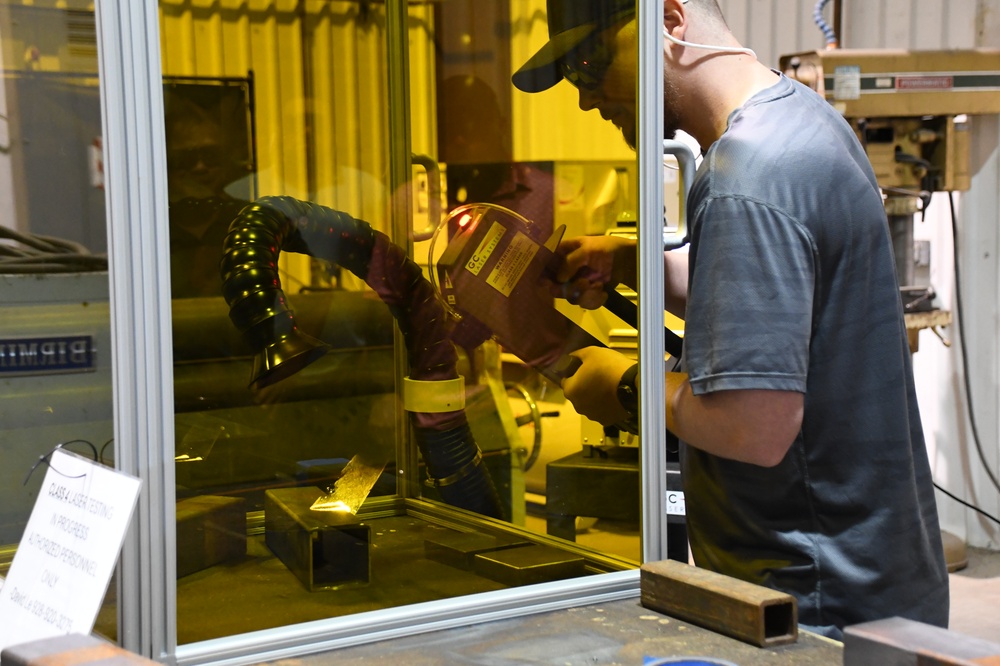
Most open-beam industrial handheld cleaners will be Class 4, but use the final machine manufacturer’s classification rather than inferring class from wattage. A source-module datasheet does not prove that the completed handheld product complies with IEC 60825-1.
Near-infrared radiation is invisible, and metal angle, surface condition and operator movement can change the reflection path. The risk assessment should establish the nominal hazard zone and consider direct and reflected beams, pulse regime, moving parts, fire, electrical hazards and the plume from the real coating and substrate.
Whenever practical, use an engineered enclosure or validated controlled area with suitable barriers, beam stops, interlocks, warning systems and access control. Eyewear is a final layer; its range and optical density must follow the actual emission band, maximum credible output, pulse regime and formal hazard assessment.
- Place local exhaust close enough to capture the plume without blocking safe movement.
- Match filtration to rust, paint, plating, oil and substrate; HEPA does not automatically control gases or vapors.
- Treat captured dust, filters and residue as a waste stream; “no abrasive media” does not mean “no waste.”
- Use qualified laser-safety and EHS personnel for the exact machine and site.
What Should You Include in a Supplier RFQ?
Check the information you can provide or require. The counter shows checklist completion, not machine suitability.
Begin with the real surface and acceptance endpoint. Add the machine and safety evidence needed to reproduce it.
Related Handheld Laser Cleaning Guides and Systems
Frequently Asked Questions About Laser Cleaning Wavelength
What is the best wavelength for a handheld laser cleaning machine?
There is no universal best wavelength. Many current handheld ytterbium-fiber cleaners use nominal wavelengths near 1064, 1070/1075 or 1080 nm. Choose the complete system that removes the real layer at the required accepted rate without crossing the substrate, safety or quality limits.
Is 1080 nm better than 1064 nm for rust removal?
Not automatically. Catalog examples often pair 1064 nm with pulsed sources and about 1080 nm with CW sources, but that is not a universal technical rule. Compare architecture, delivered energy, optics, scanning, heat accumulation and accepted output on the same rusted part.
Should I test a pulsed or CW handheld laser cleaner first?
Test pulsed first when surface control, local work or finish protection dominates. Test CW first when a robust substrate, heavy layer and large-area output dominate. If both quality and throughput are critical, run both on the same sample and use one acceptance method.
Can a handheld laser cleaner damage the base metal?
Yes. Excess fluence, dwell, overlap, passes or heat accumulation can roughen, oxidize, pit, melt or distort a surface. Start conservatively, inspect removal and substrate change separately, and stop at the written failure boundary.
Why can two 300 W pulsed laser cleaners perform differently?
They can use different source models, pulse-energy limits, pulse widths, frequencies, beam modes, scan heads, lenses, spots, fields and software. Ask for the exact delivered configuration and compare a repeated result on the same representative sample.
Does handheld laser cleaning require fume extraction?
The plume must be assessed for the actual rust, paint, oil, oxide, plating and base material. Local source capture is commonly needed because cleaning can release particles, metal oxides and coating-decomposition products. Qualified EHS personnel should specify capture, filtration and waste handling.
Sources and Technical Review
- JPT, CL2 air-cooled 200–300 W pulsed fiber laser: manufacturer example of a 1064 nm MOPA pulsed source and model-specific operating information. Accessed September 2, 2026.
- IPG Photonics, infrared nanosecond pulsed lasers and industrial single-mode CW lasers: official examples showing 1064 nm pulsed families and CW families around 1070/1075 nm. Accessed September 2, 2026.
- Raycus, CW fiber laser specification: official model example at 1080 ± 5 nm. Accessed September 2, 2026.
- Rocklin Manufacturing, portable laser cleaning systems: vendor comparison showing a 1064 nm pulsed product and separate CW products at 1080 ± 10 nm, alongside differences in power, cooling, handpiece and field. Accessed September 2, 2026.
- Kearns et al., Applied Surface Science, DOI 10.1016/S0169-4332(97)00741-1: copper-oxide removal at 1064, 532 and 266 nm, supporting the boundary that wavelength can change useful removal and surface-effect thresholds.
- Research progress in laser cleaning of aluminum-alloy surfaces: review of scan speed, overlap, focus and the balance between incomplete cleaning and substrate effects.
- Airborne particles generated during laser cleaning of corroded 304L stainless steel: primary evidence that the cleaning plume requires application-specific assessment.
- OSHA Technical Manual, Laser Hazards; IEC 60825-1:2014; IEC TR 60825-14:2022; and ANSI Z136.1-2022: product-classification, user risk-assessment and safe-use context.
Source roles are stated so a vendor specification is not mistaken for a universal standard and a research result is not treated as a ready-to-use production recipe. This guide supports screening and purchasing. Final settings, acceptance methods, extraction and laser-safety controls must be qualified for the exact machine, part and facility.
Send the substrate, unwanted layer, thickness range, photos, required finish, geometry, work area, current method and target output. Oceanplayer Laser can help plan a representative pulsed-versus-CW comparison with clear acceptance boundaries.