

Identify alloy, thickness, heat treatment, plating, edges, markings, threads, sealing areas and anything that must remain untouched.
Delicate surface decision guide
Laser Cleaning vs Sandblasting on Delicate Surfaces
Updated September 2, 2026 · 20-minute engineering guide
Often—but not automatically. Laser cleaning is a strong first candidate when selective removal and avoiding abrasive intrusion matter. Abrasive blasting remains a strong candidate when the approved end state requires a named abrasive-cleanliness or profile standard. Test both against the same removal target and accepted surface-change limits.
01
Ask what must not change before asking what must be removed.
The accepted process removes the contaminant while keeping roughness, dimensions, edges, coatings, color and downstream performance inside defined limits.
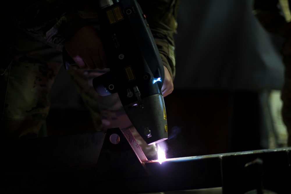
Short answer
Is laser cleaning or sandblasting better for delicate surfaces?
It depends on what must remain unchanged. Choose the first test by the substrate, removable layer, required end state and proof of no unacceptable change. A thin aluminum panel, polished cover, mold cavity and sealing land can all be delicate for different reasons.
Define rust, oxide, paint, oil, mold deposit or mixed contamination, including thickness, adhesion and any unknown legacy coating.
Preserving a polished finish is different from preparing a coating surface that needs a measured profile. State the real downstream requirement.
Choose inspection before testing: visual reference, roughness, dimensions, microscopy, coating adhesion, sealing, welding or trial-part performance.
Practical rule: start with laser cleaning for selective, media-sensitive or precision work; start with a qualified abrasive-blast route when broad removal and a specified profile are the goal; use a hybrid route when one part contains both kinds of zone. This guide uses sandblasting as the common search term. The engineering process is abrasive blasting, and silica sand is only one possible medium.
Quick comparison
How do laser cleaning and sandblasting compare on damage, profile and cleanup?
Laser cleaning uses controlled optical energy at the surface. Abrasive blasting uses high-velocity particle impact. That difference changes selectivity, surface profile, cleanup, safety controls and the types of damage that must be checked.
| Decision factor | Laser cleaning | Abrasive blasting |
|---|---|---|
| Removal mechanism | Laser-material interaction removes or loosens the surface layer through coupled thermal, ablative and mechanical effects. | High-velocity abrasive particles strike the surface and remove contamination or base material mechanically. |
| Main damage risk | Heat buildup, substrate ablation, color or oxide change, roughness change and overexposure at edges or repeated passes. | Erosion, pitting, edge rounding, media embedment, excessive profile, loss of plating or impact damage. |
| Selectivity | Can be stronger. This depends on a useful difference between how the removable layer and substrate respond, plus controlled wavelength, pulse behavior, spot size, focus, overlap and scan path. | Possible with masking and nozzle control, but media spread and rebound can make precise boundaries harder to hold. |
| Surface profile | May preserve or change roughness depending on the process window. It is not automatically equivalent to a blast-created profile. | Can deliberately create a profile for coating adhesion. The same profile can be harmful to a precision finish. |
| Geometry | A conventional cleaning head needs optical access and controlled working distance. Special delivery optics can extend access, but the actual geometry still needs qualification. | Can reach some irregular shapes, but nozzle access, local over-blast, trapped media, rebound and post-cleaning access remain concerns. |
| Residue and cleanup | No spent abrasive at the impact point, but plume, deposited particulate and used filters still require control. | Dust plus spent media, coating/rust debris and containment cleanup can be substantial. |
| Best first question | Can a stable laser window remove the layer without crossing the substrate's accepted change limit? | Can the part tolerate the selected media/process while achieving the required profile or removal rate? |
Define the risk
What exactly makes your surface delicate?
A process cannot be called gentle until the part owner defines the change that would make the part unacceptable. Build that definition from function, appearance and the next manufacturing step.
Cleaning does not restore metal already lost to corrosion. It only exposes the condition so it can be inspected and repaired.
Thin sheet or formed panel
Local heat, material loss or impact can change flatness, stiffness, fit and the edge of retained coating.
Check flatness, thickness and assembly fitMachined face, thread or sealing land
Roughness change, rounded edges, trapped residue or small dimensional loss can affect sealing and assembly.
Check dimensions, roughness and functionMold, die or textured tooling
Altered polish, vent geometry, surface texture or residue may transfer to every future molded part.
Check texture, vents and trial-part qualitySoft alloy, plating or coating to remain
Pitting, color/oxide change, coating breakthrough or uneven removal can occur at material interfaces.
Check color, coating thickness and adhesionSharp edge, engraving or traceability mark
Over-cleaning can round the edge, weaken legibility or make the boundary around a repair zone unacceptable.
Check geometry, boundary and legibilityMixed-material assembly
Elastomers, composites, glazing, electronics and adhesives can respond differently from the nearby metal.
Require material-specific engineering reviewDamage mechanisms
How do the two methods affect a delicate surface?
“Non-contact” does not mean “no effect.” Both methods have a useful operating window. Damage begins when the delivered exposure or impact crosses the accepted substrate-change limit for the tested material, layer, geometry and configuration.
Laser routeOptical dose
What changes at the surface
The removable layer absorbs energy, heats, fractures, vaporizes or is ejected. The substrate also receives energy, so the usable window must be shown with measurements—not assumed from the absence of contact.
Removal and substrate response are separated by a process window
Power or pulse energy, spot size, focus, scan speed, overlap, pattern and number of passes work together. More exposure may improve removal until it begins to alter or ablate the substrate.
- Edges and pauses can receive extra dose.
- Different paint or oxide thickness shifts the safe window.
- Dirty protective optics can change consistency.
- Reflective geometry changes both process and safety risk.
Do not copy a “safe parameter” from a different alloy, coating or optical configuration.
Blast routeParticle impact
What changes at the surface
Each particle transfers momentum and can remove contamination, coating or base material. The same action can create a useful coating profile or an unacceptable change to a precision finish.
Media and operating conditions control removal and profile
Media material, size, shape and hardness interact with pressure, nozzle, distance, angle, dwell, air quality and part support. “Low pressure” alone does not prove that a part will be preserved.
- Rebound can reach protected or hidden surfaces.
- Edges may erode faster than broad faces.
- Media can remain in threads, ports and recesses.
- Operator distance and angle affect repeatability.
Specify the complete blast process and the acceptance evidence, not only the media name.
Interactive planning aid
Which starting route fits your surface?
Select the closest description. This tool is a screening aid, not a qualified process or safety approval.
The preservation requirement defines the accepted change limit.
Area changes setup, speed and containment economics.
“Looks clean” is not an acceptance standard.
Laser needs qualified optical access; blasting needs nozzle access and media recovery.
Acceptance evidence
What must you measure to prove the surface was not damaged?
A surface can look clean and still fail the next operation. Cleanliness, roughness and coating profile are not the same result. State what the cleaned surface must do, then choose the measurement that proves it.
Set maximum appearance, roughness, dimension and edge change.
Evidence: reference panel, roughness, gauge, functionDefine residual coating, feather edge, cleanliness and accepted local profile.
Evidence: visual standard and adhesion testFollow the named cleanliness, profile, contaminant and environmental requirements.
Evidence: specification-driven coating QARemove products without hiding section loss or creating misleading damage.
Evidence: engineering inspection after cleaningProtect texture, vents, polish, dimensions and release performance.
Evidence: surface reference and trial partMeet the approved procedure and customer requirement for the exact joint.
Evidence: pre-weld check and weld inspection| Acceptance requirement | Measure before and after | Record with the result | Reject or stop when |
|---|---|---|---|
| Appearance or color | Controlled-light photos, approved visual reference and color measurement when the contract requires it. | Lighting, camera or instrument, location map and untreated control. | Color, gloss, boundary or retained finish leaves the agreed range. |
| Roughness or coating profile | Use the named roughness or blast-profile method at the same defined locations. | Instrument, settings, units, direction, range and repeated readings. | Result falls outside the coating or finish specification. |
| Dimensions and flatness | Critical thickness, edge, bore, thread, sealing land, profile or panel flatness. | Gauge method, datum, drawing location and measurement uncertainty where relevant. | Any critical dimension or assembly fit exceeds tolerance. |
| Retained plating or coating | Thickness, continuity, boundary condition and adhesion when required. | Layer identity, test method and high-risk edge or overlap locations. | Breakthrough, lifting, undercut or unacceptable feather edge appears. |
| Downstream function | Coating adhesion, welding, sealing, molding, bonding or assembly performance. | Approved procedure, sample identity and pass/fail result. | The next operation fails even when the surface looks clean. |
Measurement rule: use the same instrument, settings, units and location logic before and after cleaning. Check edges, pauses, scan overlap, nozzle overlap and the hardest-to-clean area. Ra or Rz is not automatically the same thing as coating anchor profile; use the method named by the applicable specification.
Route selection
When does each process become the better first candidate?
Use the process that proves the accepted result. The goal is not to prove that one technology always wins. The goal is to protect the high-value feature while meeting the production or coating requirement.
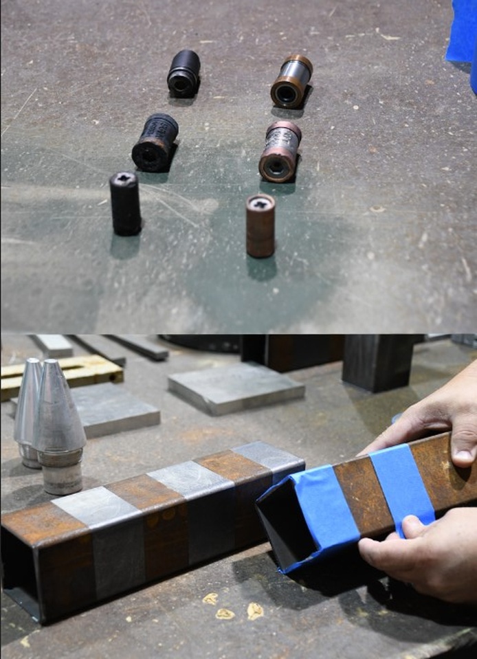
ROUTE 01 / LASER-FIRST
Choose selectivity when the feature is worth protecting
A laser pilot is a strong first candidate for localized corrosion, paint removal near a sound boundary, molds, machined features, thin panels and areas where abrasive residue is difficult to remove.
- Control wavelength/source, focus, working distance, scan path and overlap.
- Inspect edges, pauses and repeated-pass zones.
- Confirm plume capture for the material being removed.
- Record a process window tied to a specific job family.
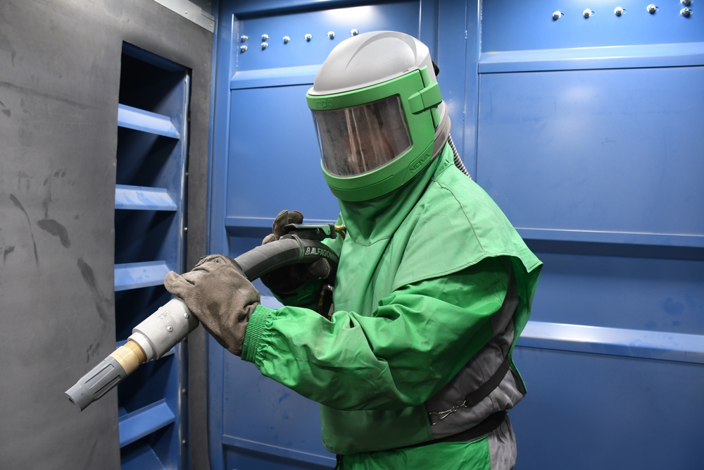
ROUTE 02 / BLAST-FIRST
Choose broad removal when profile is part of the specification
A qualified abrasive-blast trial is a strong candidate for large, open steel surfaces or coating work governed by a named abrasive-cleanliness and profile specification. Deep pits and recesses are not an automatic win: verify nozzle access, local over-blast, media recovery and inspection access.
- Name the media and complete operating condition.
- Protect edges, precision zones and nearby components.
- Measure profile and inspect for trapped media.
- Include containment, cleanup and waste in total cost.
Route 03 / Hybrid
One component can need two preparation methods
Use blasting where broad profile is required and laser cleaning around markings, machined edges, seals, localized repairs or media-sensitive details. Define the boundary so neither zone is missed or processed twice.
Prepare broad, profile-critical surfaces with the validated blast route.
Mask, fixture and define the transition before either process starts.
Use the qualified laser window and inspect both sides of the boundary.
Laser architecture
Should you choose pulsed or CW laser cleaning for a delicate surface?
Do not choose only by wattage. Pulsed and continuous-wave systems deliver energy differently, and the better route depends on the removable layer, substrate response, accepted change, coverage target and real optical configuration.
Start with a pulsed-laser trial when preservation is the main risk
Pulsed cleaning is often screened first for precision features, thinner contamination, molds, retained markings and surfaces where controlled energy delivery is more important than maximum broad-area removal.
- Record pulse energy or applicable source output, repetition rate and pulse behavior.
- Record effective spot or scan width, focus, working distance, scan speed, overlap and passes.
- Inspect roughness, color, edges and repeat-pass zones.
Consider a CW-laser trial when removal load and area are higher
CW cleaning can be attractive for heavier corrosion or larger metal areas, but a high average-power system is not automatically suitable for a delicate substrate. Heat input, dwell, travel, beam distribution and part support must be qualified.
- Record delivered power, beam profile, working distance, travel speed, path, passes and cooling conditions.
- Check thin sections, edges, corners, pauses and accumulated heat.
- Reject the route if the accepted surface or dimensional limit cannot be held.
Selection rule: compare pulsed and CW routes on the same representative part, using the same removal endpoint and the same preservation measurements. There is no universal wattage or source type that is safe for every delicate surface.
Control variables
Where a once-good result can drift into damage
Repeatability depends on more than a power setting or air pressure. Record the variables that change energy at the surface and the condition of the equipment.
Energy or impact intensity
Laser dose controls removal and substrate heating/ablation. Blast pressure and media impact control removal, erosion and profile.
Contact footprint
Spot size and overlap shape laser dose. Nozzle pattern, distance and angle shape abrasive impact.
Motion and dwell
A paused laser or slow blast pass can overprocess a small area, especially near an edge or transition.
Material condition
Layer absorption, thickness, substrate conductivity, hardness and geometry shift the usable process window.
Tool condition
Dirty optics, worn nozzles, wet/contaminated media or unstable air can change the result without an obvious setting change.
Operator and fixture
Stand-off, angle, pattern and part restraint need work instructions, training and periodic verification.
Safety and site fit
What safety, containment and waste controls does each method need?
Neither route is a zero-burden process. Industrial laser cleaning can involve Class 4 direct and reflected beam hazards, potential fire, plume and contaminated residue. Abrasive blasting involves high-velocity particles, pressurized equipment, dust, noise, spent media and removed coating/substrate debris.
The controls must match the exact machine, material, coating and worksite. Particulate filters do not automatically control every gas or vapor, and a non-silica abrasive is not automatically harmless. Base the extraction, filter media, exposure assessment and waste route on the actual material removed.
Use the relevant site requirements and competent safety professionals. See the OSHA laser-hazard guidance, OSHA abrasive-blasting guidance and ISO 11553-1:2020.
Define the controlled area, access/entry, termination, reflective geometry and abnormal conditions.
Isolate the work, control the hose/nozzle and design PPE and containment for the actual task.
Capture removed paint, oxide, oil and other residue near source; match extraction and filtration to the hazard review.
Control dust from the abrasive, coating, corrosion and substrate; plan recovery, cleanup and exposure assessment.
Protect seals, glazing, electronics, precision fits and retained coatings from heat, plume, grit and rebound.
Characterize the collected material as needed and release the area only after cleanup and inspection.
Stop before processing an unknown coating or substrate.
Review the material record, SDS, maintenance history and possible legacy hazards such as lead- or chromate-containing coatings. Identify layers that must remain, decide how residue will be collected and classified, and obtain the site hazard review. Do not run an open demonstration until the material, control plan and accepted surface-change limits are clear.
FAT and SAT acceptance
How should you test laser cleaning against sandblasting?
Prove removal and preservation at the same time. A clean-looking coupon is not enough. Use representative material and worst-case geometry, define rejection before testing, repeat the run and validate the next operation.
Record substrate, layer, critical features, area, volume, current process, required end state and rejection limits.
Define the laser controlled area and extraction or blast containment, pressure, dust and waste controls before processing.
Use the intended alloy, thickness, layer variation, edges, recesses and untreated reference zones—including the hardest case.
Record source, head, lens/nozzle, working distance, fixture, extraction, media, software and relevant maintenance state.
Trace every condition to a marked sample. Include setup, processing, handling, cleanup and inspection in the cycle boundary.
Verify removal plus roughness/profile, dimensions, edges, color, retained layers and the required downstream function.
Report samples, full settings, methods, units, repeat results, failed settings, no-go zones, maintenance and accepted output.
Verify the route with the site operator, utilities, extraction, workcell, part handling and real production constraints before release.
The pilot must be allowed to reject a process.
If no inspection result can stop approval, the trial is only a demonstration. Carry one acceptance logic from supplier FAT to site SAT, and record failed settings and no-go geometries as carefully as successful ones.
Equal-outcome economics
Which method is faster and cheaper at the same accepted result?
The faster process is not economical when it damages the surface, fails the coating requirement or moves the bottleneck into cleanup and inspection.
Price both routes from the same starting condition to the same accepted outcome. If laser cleaning needs a second profile-creation step, include it. If laser cleaning avoids major masking or rework on a precision zone, include that benefit only for that job family.
Planning formula
Cost per accepted part = setup + processing + consumables + containment + cleanup + inspection + expected reworkAlso compare accepted parts per shift, first-pass yield, annual operating cost and any incremental investment. Use your own labor, air, electricity, media, filters, cleanup, inspection and rework inputs; a calculator result is a planning estimate, not a guaranteed saving.
Open the Savings CalculatorSetupControlled area, beam termination, masking, fixture, extraction, optics readiness.Containment, masking, media/air setup, nozzle/hoses, dust collection.
OperationOperator/robot time, power, passes, process checks and protective-window checks.Operator time, compressor/air, media, nozzle wear, rebound and pass pattern.
Post-cleaningPlume residue, filters, secondary wipe, inspection and area release.Media recovery, dust cleanup, trapped-media inspection and containment removal.
Quality riskOverexposure, incomplete removal, boundary defects or failed downstream performance.Over-blast, wrong profile, edge damage, media residue or coating failure.
OwnershipMachine/extraction service, optics, safety administration, training and spares.Blast equipment, compressor, media/recovery, dust collector, PPE and wear.
Troubleshooting
Start from the defect, not from a more aggressive setting
When the result fails, compare it with the acceptance criterion. More laser power or more blast pressure can convert incomplete removal into permanent damage.
Dose, overlap, dwell or focus may be outside the safe window, or the actual coating differs from the test assumption.
Stop, compare with the reference and retest the process window.Media, pressure, angle or dwell is too aggressive, or the masking does not protect the edge.
Measure profile/geometry and test a revised media/process route.Layer thickness, absorption, scan pattern, optics or shadow geometry may be preventing consistent removal.
Map residuals and correct geometry or use a controlled additional pass.Rebound, geometry traps, unsuitable media or incomplete cleanup may create a later assembly or coating defect.
Inspect inaccessible features and redesign cleanup or process choice.Clean visual appearance did not prove the required profile, chemistry, contaminant limit or flash-rust control.
Review the coating specification and run the required acceptance test.Stand-off, path, dwell, angle, distance, part restraint or equipment condition is not controlled.
Standardize the fixture, work instruction, maintenance and inspection.Buyer checklist
Prepare an RFQ that a supplier can actually test
A strong RFQ describes the part, layer, preserved features, accepted result and evidence. Check each item as you prepare it.
Unknown items should be listed as test gates, not hidden assumptions.
RFQ readiness0 of 9
Frequently asked questions
Questions buyers ask before testing either method
It can be safer for the surface when a validated laser process removes the layer while keeping the tested substrate inside agreed change limits. It is not automatically harmless: unsuitable exposure, focus, overlap or dwell can change roughness, color, oxide state or material condition. Compare both removal and allowed surface change on a representative sample.
Yes. An aggressive blast process can roughen, pit, erode, deform or round features. Media, size, pressure, nozzle distance, angle and dwell can be controlled, but the actual alloy, thickness and finish still need a test and inspection.
It may, within a process window that matches the paint, base metal, geometry and required end state. Validate the real paint/substrate system with agreed roughness, color, dimensional or downstream tests. A generic video cannot prove damage-free removal.
Not automatically. Abrasive blasting can intentionally create a coating profile. Laser cleaning may preserve, increase or reduce roughness depending on the substrate and settings. If a coating specification requires a named profile or blast condition, measure it and obtain approval for any alternate process.
No. It avoids spent abrasive at the impact point, but removed paint, oxides, oils and deposits can create airborne plume, settled particulate and used filters. Capture, housekeeping and waste handling must match the actual removed materials.
Use the real substrate, layer, geometry and downstream requirement. Define removal and allowable surface change, include an untreated reference, run controlled process matrices, inspect boundaries and difficult features, validate the next operation and compare complete workflow cost at the same accepted result.
Continue the decision
Related Oceanplayer Laser guides and toolsThese links use the current published Oceanplayer Laser URLs and take the reader to the next practical decision.
Broader comparisonLaser Cleaner vs Sandblasting
Compare the two methods beyond damage-sensitive parts.
Read comparison → Process foundationLaser Cleaning GuideUnderstand laser types, applications and buying factors.
Open guide → Precision routePulsed Laser Cleaning MachineReview the machine family commonly evaluated for controlled surface work.
View machines → ApplicationLaser Cleaning for Metal PartsConnect surface requirements with metal-part cleaning scenarios.
Explore application → Surface qualityEfficiency vs Surface RoughnessSee why faster removal and better surface preservation can conflict.
Read analysis → Optical decisionWavelength and Spot SizeUnderstand two variables that affect interaction and coverage.
Read guide → Machine route toolPulsed vs CW ComparisonScreen the laser architecture after the application is feasible.
Open tool → Comparative pilotSend a Representative SampleShare the substrate, contamination, preserved features and accepted result.
Contact Oceanplayer Laser →Technical references
- Research Progress and Challenges in Laser-Controlled Cleaning of Aluminum Alloy Surfaces. Review of mechanisms, parameter sensitivity and the need to define removal and substrate-response boundaries.
- Characterization of Laser Cleaning of Artworks. Damage-threshold methodology for fragile surfaces; not an industrial parameter prescription.
- Research on Laser Cleaning Technology for Aircraft Skin Surface Paint Layer. A specific 2024 aluminum-alloy/coating parameter study; its tested settings should not be generalized to other systems.
- Laser paint removal and surface-response study in Optics Express. Evidence that removal can also change roughness and surface oxide condition.
- ISO 8504-2:2019. Abrasive blast-cleaning methods for steel preparation; the official scope notes impact-deformation risk for insufficiently thick cold-rolled steel.
- ISO 8503-5:2017. Replica-tape field method for measuring profile on abrasive-cleaned steel.
- NIOSH Abrasive Blasting. Official description of the process and dust from abrasive, removed material and substrate.
- OSHA: Protecting Workers from Abrasive Blasting Materials. Abrasive-blasting hazard and control context.
- OSHA Technical Manual: Laser Hazards. Controlled areas, beam termination, training and protective controls.
- ISO 11553-1:2020. Safety requirements and manufacturer information for laser processing machines.
Next step
Turn “delicate” into measurable acceptance criteriaSend the actual part information and representative samples. Oceanplayer Laser can discuss a laser-first or comparative pilot around the surface that must be preserved, not just the layer that needs to disappear.
Request a Delicate-Surface Test PlanInclude these details for a useful review:
- Material, thickness, heat treatment, coating or plating
- Rust, oxide, paint or deposit condition
- Edges, markings, finish and other features to preserve
- Required roughness, profile, cleanliness or appearance
- Downstream coating, welding, sealing or assembly test
- Photos, volume, current method and site constraints